- About Contact Sing up Log in
- Business & Industries
- Shipping & Logistics
- Markets & Trading
- Finance & Loan
- Automobiles
- Cryptocurrency
- Beauty & Skin Care
- Gift & Jewellery
- Pets & Animals
- Software & Web Development
- Digital Marketing
- Latest Technologies
- Education & Training
- Jobs & Career
- Health & Fitness
- Medical & Health
- Sports & Athletics

To verify Thevenin's theorem for the given circuit
Verification of thevenin's theorem., apparatus required.
| S.No. | Name Of The Equipment | Range | Type | Quantity |
| 1 | Voltmeter | (0-20)V | Digital | 1 NO |
| 2 | Ammeter | (0-20)mA | Digital | 1 NO |
| 3 | RPS | 0-30V | Digital | 1 NO |
| 4 | Resistors | 10K Ω,1K Ω | 1 NO | |
| 5 | Resistors | 2.2Ω | 1 NO | |
| 6 | Resistors | 330 Ω | 1 NO | |
| 7 | Breadboard | - | - | 1 NO |
| 8 | DMM | - | - | 1 NO |
| 9 | Connecting wires | - | - | Required number |
Circuit Diagram

Practical Circuit Diagrams

Theory for Thevenins Theorem
It states that in any lumped, linear network having more number of sources and elements the equivalent circuit across any branch can be replaced by an equivalent circuit consisting of Theremin's equivalent voltage source Vth in series with Theremin's equivalent resistance Rth. Where Vth is the open circuit voltage across (branch) the two terminals and Rth is the resistance seen from the same two terminals by replacing all other sources with internal resistances.
Thevenin's theorem: The values of VTh and RTh are determined as mentioned in thevenin's theorem. Once the thevenin equivalent circuit is obtained, then current through any load resistance RL connected across AB is given by, I =VTH / RTH + RL
Thevenin's theorem is applied to d.c. circuits as stated below. Any network having terminals A and B can be replaced by a single source of e.m.f. Vim, in series with a source resistance RTh
(i) The e.m.f the voltage obtained across the terminals A and B with load, if any removed i.e., it is open circuited voltage between terminals A and B.
(ii) The resistance RTh is the resistance of the network measured between the terminals A and B with load removed and sources of e.m.f replaced by their internal resistances. Ideal voltage sources are replaced with short circuits and ideal current sources are replaced with open circuits.
To find Wit the load resistor `RL' is disconnected, then VTh = [V / (R1 + R2)] x R3
To find RTH, RTH = R2 + (R1 x R3 / R1+ R3)
Thevenins Theorem is also called as Helmoltz Theorem.
- Connect the circuit as per fig (1)
- Adjust the output voltage of the regulated power supply to an appropriate value (Say 20V).
- Note down the response (current, IL) through the branch of interest i.e. AB (ammeter reading).
- Reduce the output voltage of the regulated power supply to 0V and switch–off the supply.
- Disconnect the circuit and connect as per the fig (2).
- Adjust the output voltage of the regulated power supply to 20V.
- Note down the voltage across the load terminals AB (Voltmeter reading) that gives Vth.
- Disconnect the circuit and connect as per the fig (3).
- Connect the digital multimeter(DMM) across AB terminals and it should be kept in resistance mode to measure Thevenin's resistance(RTh).
Theoritical Values
Tabular results for Thevenin's theorem:
| Theoritical Values | Practical Values |
| Vth = | Vth = |
| Rth = | Rth = |
| IL = | IL = |
Viva Questions and Answers on Thevenins Theorem
- The internal resistance of a source is 2 Ohms and is connected with an External Load Of 10 Ohms Resistance. What is Rth ?
- In the above question if the voltage is 10 volts and the load is of 50 ohms What is the load current and Vth? Verify IL?
- If the internal resistance of a source is 5 ohms and is connected with an External Load Of 25 Ohms Resistance. What is Rth?
- In the above question if the voltage is 20V and the load is of 50 Ohms, What is the load current and IN ? Verify IL ?
Latest Post

Freedom Holding Corp: A Leader in the Global Financial Market

Best Slots for Playing in Casinos by top10gambling.net

Best Crypto Casino Bonuses & Promotions by top10gambling.net

When Choose Best Payout Casinos By Suomionlinekasinot.com

All About Android Casinos By Toppnorskekasinoer.com

Elevate Your Practice: Essential Features to Seek in Chiropractic Tables for Clinics

Enhancing Business Performance with iCFO.pro
Related categories.
- Instrumentation & Measurement
- Analog & Digital Communication
- Analog Electronics
- Digital Electronics
- Electronic Devices & Circuits
- Digital Circuit System
- Digital Communication
- Electronic Circuit Design
- Microprocessor & Interfacing
- Electrical Machines 1
- Electrical Machines 2
- Power Electronics
Electrical Lab Experiment list
- 1 To conduct Open circuit vs Short circuit tests on single phase transformer
- 2 To measure the displacement vs to determine the characteristics of LVDT (Linear Variable Differential Transformer).
- 3 To plot the transistor (BJT) characteristics of CE configuration.
- 4 To find the forward vs reverse bias characteristics of a given Zener diode.
- 5 To perform Swinburne's test on the given DC machine
- 6 To verify the Kirchhoff's voltage law vs Kirchhoff's current law for the given circuit
- 7 To measure the strain using strain gauge.
Laboratory Experiment Categories
- Electrical and Electronics
- Civil Engineering
- Engineering Mechanics
- Mechanical Engineering
- Biomedical Engineering
Get all latest content delivered to your email a few times a month.
- Digital effects

- Thevenin’s Theorem
- Boris Poupet
- bpoupet@hotmail.fr
- 13 min
- 4.578 Views
Share This Article
Spread the word about this Article
Introduction
In this tutorial, we present a powerful method that can simplify through some transformation steps, complex circuits into elementary circuits and this method is commonly known as Thevenin’s theorem .
Originally, it was the German physicist Hermann von Helmholtz who first demonstrated the theorem in 1853, but history kept the name of the French engineer Leon Thevenin , who in 1883, unawarely of the work of Helmholtz, proposed a more elegant method to prove the theorem.
We will illustrate this statement in the first section where we also define the bold terms of the theorem. In the second section, we present the method to follow in detail, in order to apply Thevenin’s theorem to a circuit.
Finally, some Thevenin transformations are fully depicted in the last section with real circuits taken as examples.
Presentation and definitions
As previously mentioned, Thevenin’s theorem can only be applied to linear electrical circuits (LEC). The internal structure of LEC consist of interconnected ideal sources and resistors . Reactive components such as capacitors and inductors must be excluded since their voltage/current characteristics are not described by a linear formula.
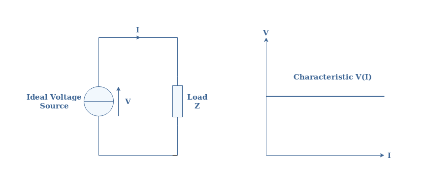
An ideal voltage source consists of a generator that delivers a constant value of voltage regardless of the current flowing in the circuit. This means that the same ideal source will always deliver the same voltage V s for any circuit connected at its terminals. This property ensures that the voltage/current characteristic of an ideal voltage source is constant and therefore is linear.
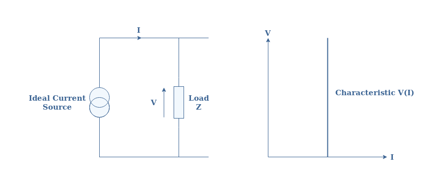
Ideal current sources can also be found in LEC and consist of generators that provide a constant value of current regardless of the voltage at their terminals. A representation of an ideal current source along with its and voltage/current characteristic is proposed in Figure 2 below:
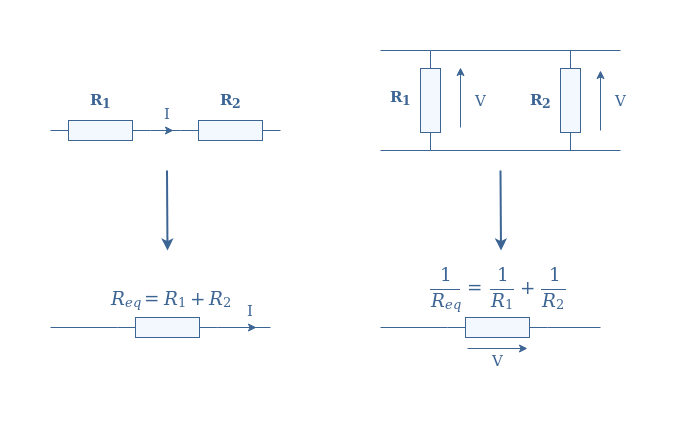
An equivalent resistor R eq is simply a concept that represents the association of a set of interconnected resistors (R 1 , R 2 ,…) into a single component. The association of resistors is dictated by two rules:
- If the resistors share the same current (in series), the equivalent resistance is the sum of the resistors.
- If the resistors share the same voltage (in parallel), the inverse of the equivalent resistance is the sum of the inverses of the resistors.
Now that these various definitions have been detailed, we can illustrate Thevenin’s theorem with the following Figure 4 :
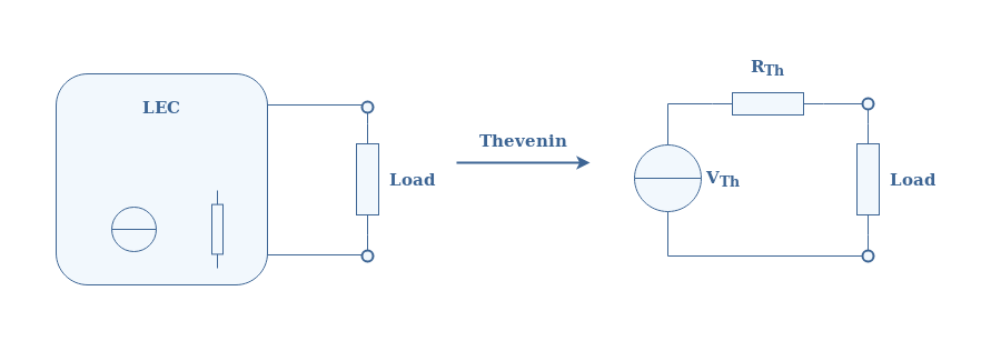
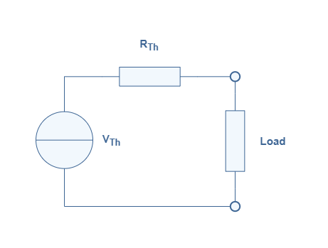
The simpler circuit obtained from the Thevenin transformation is known as the Thevenin model . The equivalent source and resistance are labeled with the subscript Th as a reference to the name of the theorem.
In the next section, we give the abstract method in order to determine this model from any LEC.
Thevenin model determination
The goal of this section is to present how the Thevenin parameters V Th and R Th are determined.
Thevenin’s voltage V Th is the voltage between the terminals of the LEC when the load is disconnected and it is also known as the open-circuit voltage.
Similarly, Thevenin’s resistance R Th is the resistance at the terminals of the circuit when the load is disconnected and all the circuit’s sources are disabled, the voltage sources are replaced with short-circuits and the current sources with open-circuits.
We propose therefore a series of steps to follow in order to determine the Thevenin model of any LEC:
- Remove the load at the terminals of the LEC
- Compute the voltage of the open-circuit
- Replace any voltage sources with short-circuits and the current-sources with open-circuits
- Compute the equivalent resistance
- Reconnect the load and draw the Thevenin model thanks to the knowledge of V Th and R Th
In the following section, we illustrate this method by determining the Thevenin model of some LEC examples with increased architecture complexity.
Thevenin’s model of some LEC
Single voltage source.
For the first example, we consider a basic LEC composed of only one voltage source and two resistors in a parallel configuration:
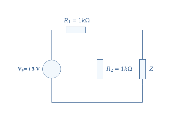
In order to determine Thevenin’s model, first of all, we proceed to steps number 1 and 2 explained in the previous section. When disconnecting the load Z from the circuit, we compute the voltage at the terminals of the LEC, that is to say across the resistor R 2 , by applying the voltage divider method:
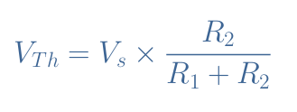
After replacing the parameters by their values, we obtain V Th =2.5 V .
We consider now the circuit by replacing the voltage source by a wire. The equivalent Thevenin resistance is the parallel association of the resistors R 1 and R 2 :
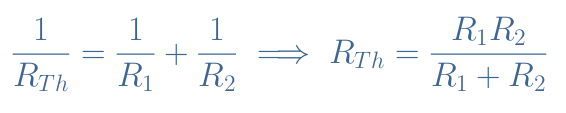
The numerical application gives R Th =500 Ω .
The circuit presented in Figure 5 can, therefore, be simplified by the equivalent Thevenin’s model presented in Figure 6 :
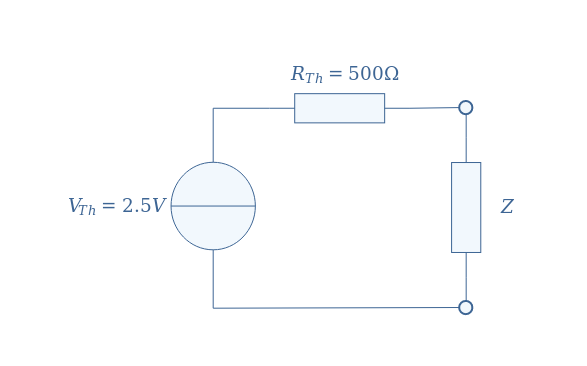
The voltage and current across any load Z are now much easier and faster to compute. As an example, if Z=100 Ω , we can use again the voltage divider formula to find V Z =0.4 V . The current is obtained by applying Ohm’s law to the resistance Z: I=V Z /Z=4 mA .
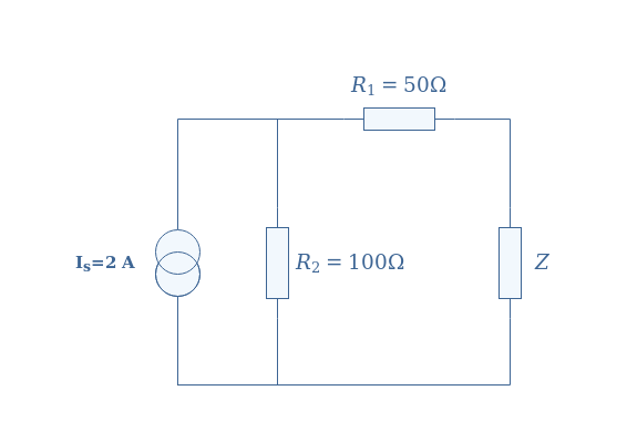
Single current source
For the second example, we consider a similar circuit than in Figure 5, but replacing the voltage source by an ideal current source and rearranging the resistors:
First of all, we disconnect the load Z from the circuit in order to determine V Th :
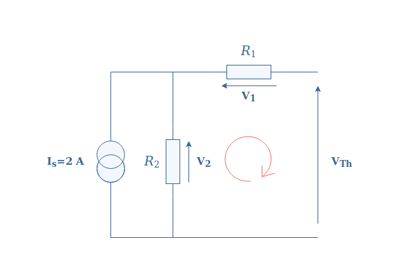
When applying Kirchoff’s Voltage Law in the loop highlighted with the red symbol, we find V Th =V 2 -V 1 . However, since the circuit is opened, no current is observed across R 1 and therefore V Th =V 2 . The current flowing in R 2 is thus equal to the current source, we finally apply Ohm’s law to R 2 in order to find V Th =100×2=200 V .
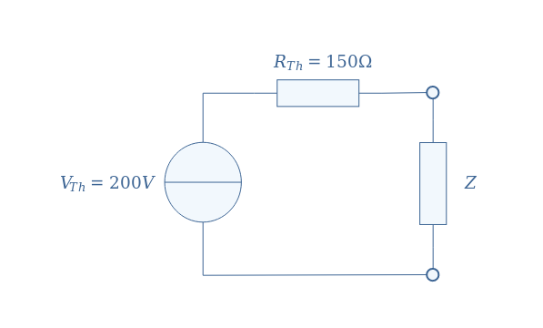
Thevenin’s resistance R Th is found by replacing the current source by an open circuit, the equivalent resistor is determined by the series association of R 1 and R 2 : R Th =R 1 +R 2 =150 Ω .
Figure 8 below illustrates the Thevenin model of the circuit presented in Figure 7:
Multi-current/voltage sources
For this last example, we propose a more complex circuit that includes both current and voltage sources:
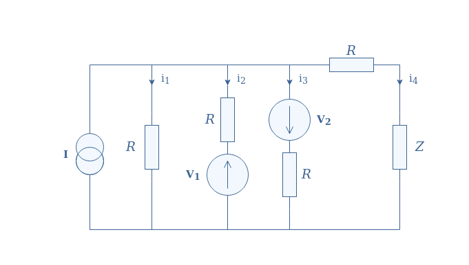
We disconnect the load in order to determine the voltage V Th . It comes automatically that i 4 =0 since the circuit becomes open. Kirchoff’s current law affirms that I=i 1 +i 2 +i 3 , moreover, we can assert thanks to Kirchoff’s voltage law that:
- i 1 =i 2 +V 1 /R
- i 1 =i 3 -V 2 /R
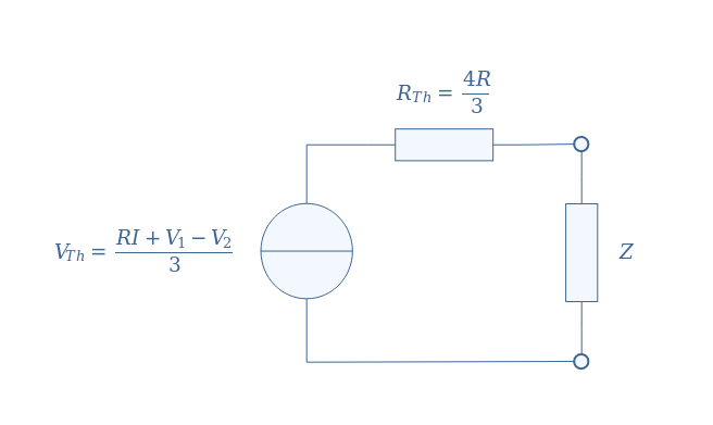
After rearranging these three equations, we can isolate i 1 =(I+V 1 /R-V 2 /R)/3. Thevenin’s voltage is simply given by R×i 1 , therefore, V Th =(RI+V 1 -V 2 )/3 .
We replace the current source by an open circuit and shorten the voltage sources in order to determine R Th :
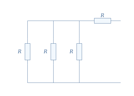
The equivalent resistance is given by the parallel association of 3 resistors in series with R, which leads to R Th =R+R/3=4R/3 .
Thevenin’s model of Figure 9 is finally given by:
“Any linear electrical circuit is equivalent to an ideal voltage source in series with an equivalent resistor .” This sentence, known as Thevenin’s theorem , was the focus of this article.
In the first section, we define the bold terms which give the framework where the theorem can be applied. A linear electrical circuit (LEC) is an interconnection of ideal sources and resistors. Ideal sources are further defined as sources with a perfectly flat voltage/current characteristic. An equivalent resistor is simply a concept that allows us to regroup a set of interconnected resistors into a single component.
In a short second section, we abstractly present how to determine the Thevenin model of any LEC by following a series of steps.
The third section illustrates, with real examples, how to transform a LEC into its equivalent Thevenin’s model. First, we clarify how to proceed for circuits containing either voltage or current sources. Finally, we demonstrate how to perform the transformation with a more complex LEC containing both sources and more resistors.
It becomes especially clear with the last example that Thevenin’s model is a powerful tool to transform complex linear circuits into elementary circuits containing only one source and a resistor.
More tutorials in DC Circuits
Current dividers, voltage dividers.
- Current Sources
- Voltage Sources
- Star-Delta Transformation
- Ohm’s Law
Electrical Units of Measure
- Maximum Power Transfer
- Norton’s Theorem

RELATED ARTICLES

- Switch skin
Home > Circuit Analysis > Thevenin’s Theorem. Step by Step Procedure with Solved Example
Thevenin’s Theorem. Step by Step Procedure with Solved Example
Thevenin’s Theorem in DC Circuit Analysis
A French engineer, M.L Thevenin , made one of these quantum leaps in 1893. Thevenin’s Theorem (also known as Helmholtz–Thévenin Theorem ) is not by itself an analysis tool, but the basis for a very useful method of simplifying active circuits and complex networks . This theorem is useful to quickly and easily solve complex linear circuits and networks, especially electric circuits and electronic networks.
Thevenin’s Theorem may be stated below:
Any linear electric network or a complex circuit with current and voltage sources can be replaced by an equivalent circuit containing a single independent voltage source V TH and a Series Resistance R TH .
- V TH = Thevenin’s Voltage
- R TH = Thevenin’s Resistance
Related Post: Norton’s Theorem. Easy Step by Step Procedure with Example (Pictorial Views)
Steps to Analyze an Electric Circuit using Thevenin’s Theorem
- Open the load resistor.
- Calculate / measure the open circuit voltage. This is the Thevenin Voltage (V TH ) .
- Open current sources and short voltage sources.
- Calculate /measure the Open Circuit Resistance. This is the Thevenin Resistance (R TH ) .
- Now, redraw the circuit with measured open circuit Voltage (V TH ) in Step (2) as voltage source and measured open circuit resistance (R TH ) in step (4) as a series resistance and connect the load resistor which we had removed in Step (1). This is the equivalent Thevenin circuit of that linear electric network or complex circuit which had to be simplified and analyzed by Thevenin’s Theorem . You have done it.
- Now find the Total current flowing through the load resistor by using the Ohm’s Law : I T = V TH / (R TH + R L ).
Related Post: SUPERMESH Circuit Analysis | Step by Step with Solved Example
Solved Example by Thevenin’s Theorem:

Calculate / measure the open circuit voltage. This is the Thevenin Voltage (V TH ) . Fig (3).
We have already removed the load resistor in figure 1, so the circuit became an open circuit as shown in fig 2. Now we have to calculate the Thevenin’s Voltage. Since 3mA current flows in both 12kΩ and 4kΩ resistors as this is a series circuit and current will not flow in the 8kΩ resistor as it is open.
This way, 12V (3mA x 4kΩ) will appear across the 4kΩ resistor . We also know that current is not flowing through the 8kΩ resistor as it is an open circuit, but the 8kΩ resistor is in parallel with 4k resistor . So the same voltage i.e. 12V will appear across the 8kΩ resistor as well as 4kΩ resistor. Therefore 12V will appear across the AB terminals. i.e,

Open current sources and short voltage sources as shown below. Fig (4)

Calculate / measure the open circuit resistance . This is the Thevenin Resistance (R TH )
We have removed the 48V DC source to zero as equivalent i.e. 48V DC source has been replaced with a short in step 3 (as shown in figure 3). We can see that 8kΩ resistor is in series with a parallel connection of 4kΩ resistor and 12k Ω resistor. i.e.:
8kΩ + (4k Ω || 12kΩ) ….. (|| = in parallel with)
R TH = 8kΩ + [(4kΩ x 12kΩ) / (4kΩ + 12kΩ)]
R TH = 8kΩ + 3kΩ
R TH = 11kΩ

Connect the R TH in series with Voltage Source V TH and re-connect the load resistor. This is shown in fig (6) i.e. Thevenin circuit with load resistor. This the Thevenin’s equivalent circuit .

Now apply the last step i.e Ohm’s law . Calculate the total load current and load voltage as shown in fig 6.
I L = V TH / (R TH + R L )
I L = 12V / (11kΩ + 5kΩ) → = 12/16kΩ
I L = 0.75mA
V L = I L x R L
V L = 0.75mA x 5kΩ
V L = 3.75V

Now compare this simple circuit with the original circuit shown in figure 1. Do you see how much easier it will be to measure and calculate the load current in complex circuit and network for different load resistors by Thevenin’s Theorem ? Yes and only yes.
Good to know: Both Thevenin’s and Norton’s theorems can be applied to both AC and DC circuits containing difference components such as resistors , inductors and capacitors etc. Keep in mind that the Thevenin’s voltage “V TH ” in AC circuit is expressed in complex number (polar form) whereas, the Thevenin’s resistance “R TH ” is stated in rectangular form.
- Maximum Power Transfer Theorem for AC & DC Circuits
- Kirchhoff’s Current & Voltage Law (KCL & KVL) | Solved Example
- Compensation Theorem – Proof, Explanation and Solved Examples
- Substitution Theorem – Step by Step Guide with Solved Example
- Millman’s Theorem – Analyzing AC & DC Circuits – Examples
- Superposition Theorem – Circuit Analysis with Solved Example
- Tellegen’s Theorem – Solved Examples & MATLAB Simulation
- SUPERNODE Circuit Analysis | Step by Step with Solved Example
- SUPERMESH Circuit Analysis | Step by Step with Solved Example
- Voltage Divider Rule (VDR) – Solved Examples for R, L and C Circuits
- Current Divider Rule (CDR) – Solved Examples for AC and DC Circuits
- Star to Delta & Delta to Star Conversion. Y-Δ Transformation
Electrical Technology
Related articles.

How to Size a Single Phase and Three Phase Transformer in kVA? Calculator

How to Calculate the Battery Charging Time & Battery Charging Current – Example

How To Calculate Your Electricity Bill. Electric Bill Calculator with Examples

How to Find the Proper Size of Wire & Cable In Metric & Imperial Systems

Automatic Street Light Control Circuit using LDR & Transistor BC 547

Emergency LED Light Circuit – DP-716 Rechargeable 30 LED’s Lights Schematic
108 comments.
thanks, good easy to understand.but the voltage source have more than one. how to do it.
It is simple example for ref & explanation purpose only…Wait for upcoming posts….Thanks
Surely when the load resistor is replaced the circuit changes and the 8k and 5k are in parallel with the 4k causing the cu
Surely when the load resistor is replaced the circuit changes and the 8k and 5k are in parallel with the 4k causing the current and voltage to change oops just figured it out the long way and the 5k gets 3.75 out of the 9.75 volts across that part of the circuit your way of showing thevenin is better thank you
Thanks for your kind words…
If the voltage source is more than one you calculate two components of Nortons current that is I’ and I”, add them to get the total Nortons current and repeat the procedure explained above.
Admin. You are doing great work. Your posts related to electricals are easy to learn. . . Keep updating. . .
Thanks for appreciation…
Thevenin's Theorem is not very intuitive for a newbie, good to have this nice easy to follow explanation.
simple and good steps for easy understanding
Good one for basic understanding of theorems :)<br />
How did u get 3mA?
I = V / R …<br />= 48V / (12kΩ + 4kΩ )<br />= 3mA <br /><br />So 3mA Current will flow in both 12kΩ and 4kΩ resistors as this is a series circuit because current will not flow in the 8kΩ resistor as it is open<br /><br />
If the rounded off value of 3mA is used to find Vth you get 12V. If the less rounded off value of 3.273mA is used we’d get 13V.
when the load terminals are open then all the current passes through only first circuit and the current is from v=i/r can be calculated
1st of all find req than by v=ir , i=v/r we can get the value of current
Thanku. <br />What happens when there is 2 voltage sources?
Use Kirchhoff law
i am proud that u can make this subject such intresting..<br /><br />hope many teachers of ur kind should be there..<br /><br />i am learning this during my job period ..if it was during my college it would have been a big deal for me..<br /><br />anyway thanks!!
hope many teachers of ur kind should be there..<br /><br />i am learning this during my job period ..if it was during my college it would have been a big deal for me..<br /><br />anyway thanks!!
Dhuurrrrrr!!
tq admin..mechanical stdent frm malaysia :)
Most welcome dear….
How can I find you in Facebook?
Here is the official Facebook Page of Electrical Technology .
step by step process is easy way for students to understand the problem
Great job there, sometimes is easy to understand through other source.
thank you sir…. this is really a helpful information..
thank u very much sir……
plesae provide telligan’s theorem
Thanks for your very informative post. I had a very bad going with this topic, but now I can assure keep my hands dirty on complex circuits related to this phenomenon by using your idea.
outstanding sir
it is very easy to understand the concept,but if more than one voltage sources are present then how will be the solution and procedure
It is too much easy
boss i love this your tutorials its the best i have ever seen you simplified the sturf to the last five star 4 u *****
best tutors site
Thank you…
sir this is awesome sir i had clarify my doubts succesfully
it is soo easy to understand
Thank you very much!!!
could you give another exercise with 2 suppliers? and show steps
Thumps up to yo tutorials,now I understand the theorem way better than I previously did.Thanx so Much
Thanks for appreciation….
why you solve 12 and 4 as parallel?
If you see in step 4, 8kΩ resistor is in series with a parallel connection of 4kΩ resistor and 12k Ω resistor. i.e. If you solve for the parallel connection of 4kΩ resistor and 12k Ω, It becomes in Series with 8kΩ.
In step 2, The Circuit is Open, Hence, Current will not flow in 8kΩ, Therefore, That’s Why it is in parallel with 4kΩ.
will you please add step by step procedure for dual loops that will help alot Thanx in advance
Great job. you make the determination of thevenin’s voltage is very very easy. Thank you…
I could not solve even a single problem .But this helped me a lot .Thank u
Glad it helps You….
Thanks…
can i get more relevant problems using thevinin’s theorem & may i know that thevinin’s theorem can use for AC supplied circuits.
Yes…. It can be used on both AC and DC Circuits,,, We will post about Thevinin’s theorem about AC Circuits in coming days… Thanks
Told how to solve thevinins them in ac by using kvl.
please inform more and more about electrical and electronics
sir I have a confusion when you calculate Rth because I dont think that Rth=8+4||12. But It should be Rth=12+4||8. Am I wrong Sir ?, if so then please guide me. Thanks Ankit
As mentioned above that We can see that 8kΩ resistor is in series with a parallel connection of 4kΩ resistor and 12k Ω resistor. i.e.: 8kΩ + (4k Ω || 12kΩ)
Saqib Javeed is Right…. Thanks
let me know if you want to know more… Thanks
simply superb
Thank you very much, this was the best explanation available on the internet
Thanks for appreciation …
Was very helpful…thanks a billion times ?
Most Welcome….
Awesome explanation. It’s very useful to us, Thank you!!
Most welcome… And thanks for appreciation….
have we already been provided with 3Am or you have solved it? if you have solved it how have you done it?? a ain’t sure if I have followed you on that one
It is not provided. In Step 2, You may see that this is an Open Circuit, I.e. Current will not flow in the 8kΩ. So the circuit of 48V, 4kΩ and 12kΩ becomes a series circuit. By using Ohms Law, (I = V/R), We found the value of current as 3mA. Thanks
what will be total R in the circuit if 4k shud the load resistance in revolving towards the source
You may just change the value of the resistance and solve again same as above…. No Difficulties…. :)
you said 8k resistor is parallel to 4k resistor in step 2.in step 4 you said 8k resistor is sereis to 4k.why?
Yes Dear…. If you see in step 4, 8kΩ resistor is in series with a parallel connection of 4kΩ resistor and 12k Ω resistor. i.e. If you solve for the parallel connection of 4kΩ resistor and 12k Ω, It becomes in Series with 8kΩ.
In step 2, The Circuit is Open, Hence, Current will not flow in 8kΩ, Therefore, That’s Why it is in parallel with 4kΩ. Thanks. let me know if you want to know more… Thanks
wow. thank you. now i understand. :)
thank you for this. but how about 3 sources using this theorem?
Please how was the 3mA current gotten ?
can you explain to me about how did you get 12V as it is 48V?
IT IS GOOD BUT I WILL LIKE IT IF IT SOLVED USING SMALL NUMBERS LIKE 3,4,2 TO MAKE IT LOOK MORE SIMPLER
Thevenin made simply. thanks dear.
A/C to my point of view, Its very simple and easy method for understanding..
Simplified example…great work
if I find current across 5 ohm resister there is a greater value then the total load current that is 0.75 can anyone answer
thanks for the example.
thank you dear
A really Understanding work!
Thanks for keeping the simplicity in the explination I thoroughly understood the conpect.
Thanks soooooo much, it really help me out.
Thank you so much to help me in easy way
And if there is an ammeter in parallel with the resistance, then what to do
Really good
If there are a voltage or current source between A & B terminals or in the place of load resistor, Then how can i solve this????????
VERY SIMPLY AND THOROUGHLY EXPLAINED THE CONCEPT OF THEVENINS THEOREM. PLEASE INCLUDE THE NOTES OF TWO POLE NETWORKS ALSO
Am happy for the steps of thevenins i cam now calculate but following the steps
sir please tell me….is this the right and only method to solve problems by thevenin’s theorem?
Yes! But you can analyze the same problem by different methods as well.
can you please tell me the different methods sir?
please respond quick!!
Very good explanation. I tend to solve complex circuits using Kirchoff’s laws…Are there particular cases when one method is favourably used instead of the other? ( I have not read all posts…maybe you have already gone into this)
how did u get 3mA
3mA current will flows in both 12kΩ and 4kΩ resistors as it is a series circuit because current will not flow in the 8kΩ resistor as it is open (Fig 2)
thankyou its help full. request.. how can I calculate if there are voltage source in the circuit?
thank u so much
Where does the load resistor come from? Can any load resistor be used?
Hi Admin If point A and point B are at 4kohm, how to get V(TH) and R(TH)? Thanks
Sir RL=5kom kese find ?
It is the given data in the first circuit (fig 1).
Sr i need more explanation on how you get 12v
Inspiring lessons, Thanks so much
Leave a Reply Cancel reply
Your email address will not be published. Required fields are marked *

Verification of Thevenin Theorem
Aim of the experiment.
To Verify Thevenin's Theorem.
IMAGES
VIDEO
COMMENTS
Analog Signals, Network and Measurement Laboratory. ... Objective: To Verify Thevenin's Theorem. Its provides a mathematical technique for replacing a given network, as viewed from two terminals, by a single voltage source with a series resistance. ... The simulator for this experiment is designed based on JavaScript platform combined with ...
Experiment No. 3 Date : VERIFICATION OF THEVENIN'S THEOREM Aim: To verify Thevenin's theorem and to find the full load current for the given circuit. Apparatus Required: Sl.No. Apparatus Range Quantity 1 RPS (regulated power supply) (0-30V) 2 2 Ammeter (0-10mA) 1 3 Resistors 1K , 330 3,1 4 Bread Board -- Required 5 DRB -- 1
Experiment No.5 Thevenin's Theorem 1.1 Objective: The objective of this exercise is to examine the use of Thévenin's Theorem to create simpler versions of DC circuits as an aide to analysis. Multiple methods of experimentally obtaining the Thévenin resistance will be explored. 1.2 Components 2. Digital Multimeter. 3.
EXPERIMENT 5 THÉVENIN EQUIVALENT CIRCUITS AND MAXIMUM POWER TRANSFERINTRODUCTIONThévenin's Theorem states that a two terminal circuit may be replaced by an equi. lent two terminal circuit consisting of a voltage source and a series resistance. The Thévenin equivalent circuit will deliver the same current and.
Thevenin's theorem: The values of VTh and RTh are determined as mentioned in thevenin's theorem. Once the thevenin equivalent circuit is obtained, then current through any load resistance RL connected across AB is given by, I =VTH / RTH + RL. Thevenin's theorem is applied to d.c. circuits as stated below. Any network having terminals A and B ...
Thevenin's theorem may be stated as follow, "The current flowing through a load resistance RL connected across any two terminal A and B of a linear, active, bilateral network is given by Voc/ (Ri+RL) where Voc is the open circuit voltage (i.e. voltage across the two terminals when RL is removed) and Ri is the internal resistance of the network as viewed from back into the open circuited ...
2 A typical laboratory signal generator has a 50 \(\Omega\) internal impedance, and using this value would be more accurate than just replacing the source with a shorting wire. This page titled 5.4: Thévenin's and Norton's Theorems is shared under a CC BY-NC-SA 4.0 license and was authored, remixed, and/or curated by James M. Fiore via source ...
Thévenin's theorem, named after Léon Charles Thévenin, is a powerful analysis tool. For DC, it states: Any single port linear network can be reduced to a simple voltage source, Eth, in series with an internal resistance, Rth. Any single port linear network can be reduced to a simple voltage source, E t h, in series with an internal ...
As seen, V.O.C. = drop across R 2 = IR 2 where I is the circuit current when A and B is open. I = E r + R 1 + R 2. V o. c. = I ∗ R 1. V o. c. = E ∗ R 2 r + R 1 + R 2. It is also called Thevenin voltage (V th). 3) Now, imagine the battery to be removed from the circuit, leaving its internal resistance r behind and redraw the circuit as shown ...
Obtaining VTH and RTH, construct the circuit of figure 2. Set the value of RTH using a Decade Resistance Box. Measure the VL for this circuit and compare it to the VL obtained from circuit of figure 1. This verifies the Thévenin theorem. Repeat steps 1(b) to 1(f) for RL = 3.3 KW. Verifying the Maximum Power Transfer theorem:
Laboratory Manual - DC Electrical Circuit Analysis (Fiore) 11: Thévenin's Theorem Expand/collapse global location ... The objective of this exercise is to examine the use of Thévenin's Theorem to create simpler versions of DC circuits as an aide to analysis. Multiple methods of experimentally obtaining the Thévenin resistance will be ...
Thevenin's theorem affirms that any linear electrical circuit is equivalent to an ideal voltage source in series with an equivalent resistor. We will illustrate this statement in the first section where we also define the bold terms of the theorem. In the second section, we present the method to follow in detail, in order to apply Thevenin ...
laboratory experiment we are going to take a look at Thevenin and Norton equivalent circuits, ... Thevenin's Theorem: Any combination of sources and resistances with two terminals can be replaced by a combination of a single voltage source (Thevenin voltage) in series with a single ... Thevenin resistance (the resistance between terminals a ...
Solved Example by Thevenin's Theorem: Example: Find VTH, RTH and the load current IL flowing through and load voltage across the load resistor in fig (1) by using Thevenin's Theorem. STEP 1. Open the 5kΩ load resistor (Fig 2). STEP 2. Calculate / measure the open circuit voltage. This is the Thevenin Voltage (VTH).
in the Physics 252 laboratory course. The measurements are extracted from a linear fit of output voltage versus output current data and yield a Thévenin resistance of RTh = 0.070 Ω ± 5% and a Thévenin voltage of VTh = 3.068 V ± 0.12%. I. Introduction This report summarizes the laboratory verification of Thévenin's theorem as applied
In electrical circuit theory, Thévenin's theorem for linear electrical networks states that any combination of voltage sources, current sources and resistors with two terminals is electrically equivalent to a single voltage source V and a single ser
LIST OF EXPERIMENTS 1. Experimental verification of Kirchhoff's voltage and current laws 2.Experimental verification of network theorems (Thevenin, Norton, ... To practically verify the Thevenin's theorem for the network with the theoretical calculations. Apparatus Required: Sl.No Name of the Range Type Qty Apparatus 1. Milli Ammeter (0-20 ...
The Thevenin's theorem EMT 1150. Experiment # 11/ 4/ 2020. Table of Contents. Objective Required Materials Procedure/ Data Multisim Work Conclusion. ... EMT-1150 LAB#10 2 - thevenin theorem; EMT-1150 lab 4 - ohms law measurements; English (US) United States. Company. About us; Ask AI; Studocu World University Ranking 2023;
Aim of the experiment. To Verify Thevenin's Theorem. Community Links Sakshat Portal Outreach Portal FAQ: Virtual Labs. Contact Us Phone: General Information: 011-26582050 Email: [email protected]. Follow Us. AGPL 3.0 & Creative Commons (CC BY-NC-SA 4.0)
Thevenin's Theorem Lab Experiment | Basic Electrical and electronics Engineering Lab | BEEE Lab
The first part of the experiment was all about proving Thevenin's Theorem and understanding the concepts behind the theorem. Firstly, the circuit in Fig. 1 was the ideal circuit for construction. The voltage of the power supply was set to 12 V and was connected to three resistors (3 kΩ, 2 kΩ, 1 kΩ), and the load RL (470 Ω).
experiment to prove Thevenin's theorem with software simulation which is NI Multisim. all of it is compiled in the word of pdf form with the given manual. ... Lab Report. Experiment 3: Thevenin's Theorem. Name1 : DION (I20019576) Program : BMEGI. Course Code : EGR. Session : January 2021. Lecturer : Dr. Jeya Gopi Rahman.