
CIE IGCSE Physics Notes
3.1.5 utilizing ripple tanks in wave studies, what is a ripple tank.
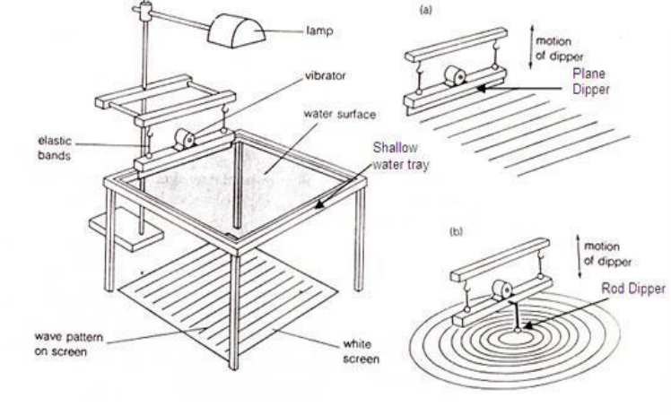
A ripple tank is a shallow, transparent container filled with water, used to study wave motion. It provides a two-dimensional view of wave patterns, making it easier to observe and understand wave phenomena.
Creating Waves in a Ripple Tank
Waves are generated in ripple tanks using a vibrating object such as a rod or a motorised wave generator.
The frequency and amplitude of these waves can be varied, allowing exploration of different wave behaviours.
Understanding Wave Behaviours
Ripple tanks demonstrate three key wave behaviours: reflection, refraction, and diffraction, each playing a vital role in understanding wave physics.
Reflection of Waves
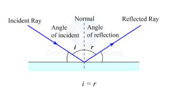
Reflection is the bouncing back of waves upon encountering a barrier.
The law of reflection states that the angle of incidence (the angle between the incident wave and the normal) is equal to the angle of reflection (the angle between the reflected wave and the normal).
Refraction of Waves
Refraction occurs when waves pass from one medium to another, resulting in a change in speed and direction.
In a ripple tank, refraction is observed by creating regions of different depths, as the wave speed changes with depth.
Diffraction of Waves
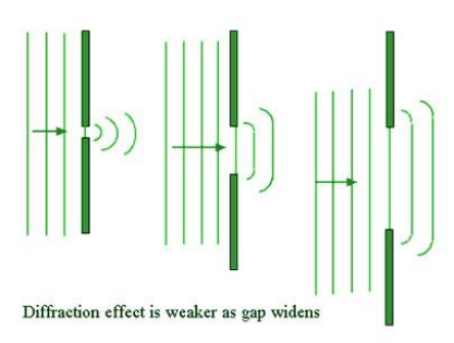
Diffraction is the bending of waves around obstacles or through gaps.
The extent of diffraction is influenced by the size of the obstacle or gap relative to the wave's wavelength.
Impact of Depth Changes on Wave Speed
How depth affects speed.
Wave speed in water is affected by the depth of the water. In shallower regions, waves slow down due to increased friction with the tank's bottom.
This phenomenon is crucial for understanding wave behaviour in varying environmental conditions.
Observations in Ripple Tanks
By creating areas of different depths within the ripple tank, students can visually observe the slowing down or speeding up of waves.
This is particularly relevant for studying tidal movements and wave behaviours near coastlines.
Role of Gap Size and Edges in Diffraction
Gap size influence.
The size of the gap through which the wave passes is critical in determining the diffraction pattern.
If the gap size is similar to the wavelength, significant diffraction occurs, resulting in a wide spreading of the wave.
Edges and Diffraction
When waves encounter sharp edges, they bend around them, exhibiting diffraction.
The amount of bending, or diffraction, depends on the wave's wavelength and the sharpness of the edge.
Practical Applications of Ripple Tanks
Demonstrating real-world phenomena.
Ripple tanks are used to simulate various natural occurrences, such as the way ocean waves interact with different coastal features.
They also help in visualising seismic wave behaviours during earthquakes, enhancing understanding of these complex processes.
Enhancing Understanding of Wave Properties
Experiments in ripple tanks allow for manipulation of wave characteristics, providing a deeper insight into wave dynamics.
The visual and interactive nature of these experiments makes theoretical concepts more accessible and understandable.
Setting Up a Ripple Tank Experiment
Equipment and setup.
Essential components of a ripple tank setup include the tank itself, a light source for shadowgraphy, and a wave generator.
The light source casts shadows of the waves onto a screen or surface, making wave patterns more visible.
Conducting Experiments
Students can experiment by altering wave frequencies, introducing different barriers or obstacles, or changing the water depth.
Recording and analysing the wave patterns provide practical experience in wave physics.
Safety and Maintenance
Ensuring safety.
Safety measures are essential to prevent electric shock, especially when using electrical components near water.
Careful handling of the ripple tank and associated equipment is necessary to avoid accidents and damage.
Regular Maintenance
Routine cleaning of the ripple tank ensures clear visibility and accuracy in observing wave patterns.
Proper storage and maintenance of the equipment ensure its longevity and effectiveness in teaching environments.
Ripple tanks serve as an invaluable resource in IGCSE Physics education. By facilitating hands-on learning experiences, they help students visualise and understand complex wave behaviours, which is pivotal for a thorough grasp of wave physics. The use of ripple tanks in demonstrating reflection, refraction, and diffraction, along with the effects of depth and gap size on wave behaviour, provides students with a comprehensive understanding of wave dynamics. These experiments not only reinforce theoretical knowledge but also encourage curiosity and a deeper appreciation for the physics of waves.
Can ripple tanks be used to demonstrate the properties of sound waves?
Ripple tanks are primarily designed to demonstrate the properties of surface water waves, which are transverse waves. While they can't directly model sound waves (which are longitudinal waves), they offer an analogy for understanding certain behaviours that are common to all waves, such as reflection, refraction, and diffraction. For instance, when a ripple tank is used to demonstrate diffraction, the spreading of water waves through a gap can be analogous to how sound waves spread out after passing through a doorway. However, it's crucial to remember that this is a conceptual analogy; the physical mechanisms of water waves in a ripple tank and sound waves in air are fundamentally different. In a classroom setting, ripple tanks provide a visually accessible way to explore wave behaviours that are otherwise challenging to observe with sound waves.
Why do waves in a ripple tank form circular patterns when a single drop of water is used as the source?
When a single drop of water impacts the surface in a ripple tank, it creates waves that radiate outward from the point of impact. These waves are circular because the point of disturbance acts as a central point, sending out disturbances in all directions uniformly. The circular wavefronts represent crests of the waves moving away from the source. This phenomenon is a result of the water molecules oscillating and transferring energy to neighbouring molecules in a symmetrical pattern around the point of impact. The uniformity in the distribution of energy and the isotropic nature of the fluid (water) result in these concentric circular patterns. This observation in a ripple tank is a clear demonstration of the principle that waves travel outwards from a point source in circular patterns in isotropic mediums.
How does the frequency of the wave source affect the wave patterns observed in a ripple tank?
The frequency of the wave source in a ripple tank has a significant impact on the wave patterns observed. A higher frequency source produces waves that are closer together, meaning the wavelength is shorter. This results in a larger number of wavefronts within a given area of the tank. Conversely, a lower frequency source generates waves that are further apart, indicating longer wavelengths. This frequency-wavelength relationship is crucial for understanding wave behaviour. High-frequency waves can result in more intricate interference patterns, especially when two wave sources are used. This can be particularly enlightening when studying phenomena like constructive and destructive interference. Moreover, the frequency of the waves also affects their interaction with barriers and gaps. For instance, high-frequency waves with shorter wavelengths diffract less compared to low-frequency waves with longer wavelengths when passing through the same size gap.
What is the significance of using a strobe light in ripple tank experiments?
A strobe light is a powerful tool in ripple tank experiments, particularly for visualising wave motion at different frequencies. When the frequency of the strobe light matches or is a harmonic of the wave frequency, it creates a ‘frozen’ wave pattern, making it easier to observe and analyse the wave characteristics. This effect is due to the strobe light illuminating the waves at specific intervals, effectively creating a snapshot of the wave at different phases of its motion. This technique allows for a detailed examination of wave properties like wavelength, amplitude, and wave speed. It's especially useful in demonstrating phenomena such as standing waves or interference patterns, where precise measurements and observations are crucial. The use of a strobe light in ripple tank experiments significantly enhances the educational value by allowing students to observe dynamic wave behaviours in a quasi-static way.
Can ripple tanks illustrate the principle of superposition of waves? How?
Ripple tanks are an excellent tool for illustrating the principle of superposition of waves. The superposition principle states that when two or more waves meet, the resultant displacement at any point is the sum of the displacements of the individual waves at that point. In a ripple tank, this can be demonstrated by creating waves from two separate points. As these waves intersect, they overlap and interact with each other. Where wave crests meet crests (or troughs meet troughs), constructive interference occurs, leading to waves with a larger amplitude. Conversely, where crests meet troughs, destructive interference happens, resulting in decreased amplitude or flat spots. This visual demonstration in a ripple tank provides a clear and tangible example of how waves interact in space, embodying the superposition principle. Such experiments are invaluable for understanding wave interactions in more complex systems, like sound waves, light waves, and even quantum mechanics.
Practice Questions
In a ripple tank experiment, a student observes that waves passing through a gap in a barrier spread out and form a pattern that covers a wider area compared to when there is no barrier. Explain why this spreading occurs and describe the factors that affect the extent of this spreading.
This spreading of waves is known as diffraction, which occurs when waves pass through a gap or around an obstacle. The extent of diffraction primarily depends on the wavelength of the waves and the size of the gap. If the gap size is comparable to the wavelength, the waves undergo significant diffraction, resulting in a wider spread. Conversely, if the gap is much larger than the wavelength, the diffraction is less noticeable. This concept is crucial in understanding wave behaviours, as it demonstrates how waves can bend and spread out, a phenomenon observed in various real-world scenarios like sound waves passing through doorways or water waves interacting with gaps in breakwaters.
Describe an experiment using a ripple tank to demonstrate the effect of water depth on wave speed. Include details on how you would set up the experiment and the expected observations.
To demonstrate the effect of water depth on wave speed in a ripple tank, first, create a gradient in water depth across the tank. This can be achieved by placing a sloped object at the bottom of one end of the tank. Next, generate waves at one end of the tank using a wave generator. As the waves travel from the deeper to the shallower part of the tank, observe the change in wave speed. In deeper water, the waves travel faster due to less friction with the tank's bottom. As the waves enter the shallower region, they slow down. This experiment visually demonstrates how water depth affects wave speed, an important concept in understanding wave dynamics in different environments, such as in oceans and lakes.

Shubhi is a seasoned educational specialist with a sharp focus on IB, A-level, GCSE, AP, and MCAT sciences. With 6+ years of expertise, she excels in advanced curriculum guidance and creating precise educational resources, ensuring expert instruction and deep student comprehension of complex science concepts.
Hire a tutor
Please fill out the form and we'll find a tutor for you.
SITEMAP * HOME PAGE * SEARCH * UK KS3 level Science Quizzes for students aged ~13-14
UK GCSE level Biology * Chemistry * Physics age ~14-16 * Advanced Level Chemistry age ~16-18
School-college Physics Notes: Waves 11. Ripple tank experiments
| in a Doc Brown's Physics exam study revision notes: Investigating waves using a ripple tank: measuring the frequency, speed and wavelength of water waves in a ripple tank. in a
- common points for all three wave experiments described - so you can clearly observe the waves. or is suspended over and into the water of the ripple tank. so that you can directly set the frequency of paddle oscillation i.e. frequency of the ripple waves.
.
.
(also , the wavelength too) and employing the use of a and a screen below the tank. .
=
.
= Know how to make measurements or calculations from observations of the frequency, speed or wavelength of the water waves.
] below, maybe quicker than navigating the many sub-indexes for UK KS3 science students aged ~12-14, ~US grades 6-8 * * for UK GCSE level students aged ~14-16, ~US grades 9-10 for pre-university age ~16-18 ~US grades 11-12, K12 Honors
|
| specific physics words or courses e.g. topic, module, exam board, formula, concept, equation, 'phrase', homework question! anything of physics interest! This is a Google generated search of my website |
TOP OF PAGE
CIE iGCSE Physics (0625) Unit 3. Waves Study Notes -2023,2024&2025
Chapter 3 Waves
3.1 General properties of waves
1. Know that waves transfer energy without transferring matter 2. Describe what is meant by wave motion as illustrated by vibrations in ropes and springs, and by experiments using water waves 3. Describe the features of a wave in terms of wavefront, wavelength, frequency, crest (peak), trough, amplitude and wave speed 4. Recall and use the equation for wave speed v=fλ 5. Know that for a transverse wave, the direction of vibration is at right angles to the direction of propagation and understand that electromagnetic radiation, water waves and seismic S-waves (secondary) can be modelled as transverse
6. Know that for a longitudinal wave, the direction of vibration is parallel to the direction of propagation and understand that sound waves and seismic P-waves (primary) can be modelled as longitudinal 7. Describe how waves can undergo: (a) reflection at a plane surface
(b) refraction due to a change of speed
(c) diffraction through a narrow gap
8. Describe the use of a ripple tank to show: (a) reflection at a plane surface (b) refraction due to a change in speed caused by a change in depth (c) diffraction due to a gap (d) diffraction due to an edge
9. Describe how wavelength and gap size affects diffraction through a gap 10. Describe how wavelength affects diffraction at an edge
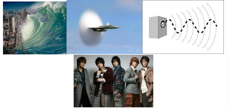
• Which of the picture above shows a wave in action? • Waves transfer energy between points without transferring matter • Best way to visualize this would be to use a slinky and shake it up and down. • You will see a wave but the rings on the slink does not actually travel with the wave.
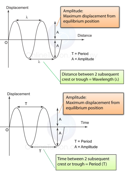
• Amplitude (A) is the maximum displacement from the original position. • The SI unit for amplitude is in meters. • Wavelength (λ) is the horizontal distance between two points that are in phase. • The SI unit for amplitude is in meters as well. • The period (T) is the time taken for the wave to complete a cycle or return to its original displacement. • The SI unit for periods is seconds. • Frequency (f) is the number of complete cycles in a second (i.e., how many times did the wave go up, down and up again or down, up, and down again in 1 second). • The SI unit for frequency is hertz (Hz) OR \(seconds^{-1}\) • Hence the relationship between frequency (f) and period (T) is
\(f=\frac{1}{T}\)
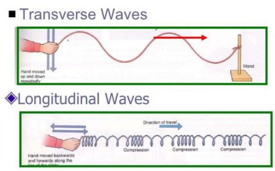
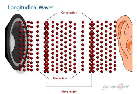
• The speed of a wave can be calculated using the following equation Speed (m/s) = Frequency (Hz) x Wavelength (m) v = f x λ • There are two types of waves. • In a transverse wave, particles vibrate perpendicular the lines of motion and consists of a series of “peaks” and “valleys”. • In a longitudinal wave, particles vibrate along the lines of motion and consists of a series of compression and expansion.
• Examples of transverse waves include; electromagnetism, water waves and S-seismic waves. • Examples of longitudinal waves include: sound waves and P-seismic waves. • A wave must be able to demonstrate these three phenomena in order to be considered as a wave. • Reflection is the change of direction when a wave collides with a reflective barrier.
• Refraction is the change of direction when the wave goes through a change of medium. • Refraction occurs when the direction of motion is not perpendicular to the border between the deep and shallow regions. • The speed of the water changes when there is a change in the depth of the water.
• From deep to shallow waters, the wave’s speed decreases as the wavelength becomes shorter. • From shallow to deep waters the wave’s speed increases as the wavelength becomes longer (Hint: recall v = fλ ). • One way to imagine this is to picture deep waters as a broad road allowing many cars to travel and shallow water as a narrow road causing a jam.
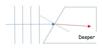
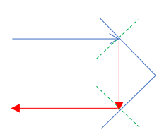
Hint: 1) Draw a line representing the direction of the wave propagation first (blue arrow) 2) Then only draw the normal line (green arrow)
• Diffraction is shown when a wave spreads when the wave passes through an opening or an edge. • Diffraction increases when the size of the gap decreases or the wavelength of the waves increases.
• A ripple tank can be used to demonstrate the above three phenomenon.
3.2.1 Reflection of light
1. Define and use the terms normal, angle of incidence and angle of reflection 2. Describe the formation of an optical image by a plane mirror, and give its characteristics, i.e. same size, same distance from mirror, virtual 3. State that for reflection, the angle of incidence is equal to the angle of reflection; recall and use this relationship
4. Use simple constructions, measurements and calculations for reflection by plane mirrors
• Light is a wave because it undergoes reflection, refraction and diffraction. • Reflection
• Types of mirrors
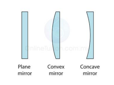
• Reflection in plane mirror
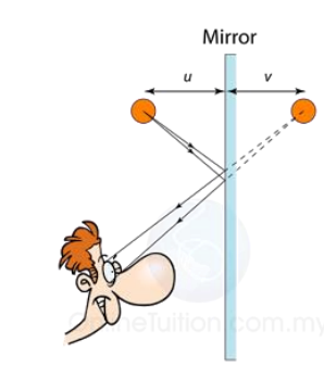
• The image form is upright, virtual, laterally inverted and same size as object.
3.2.2 Refraction of light
1. Define and use the terms normal, angle of incidence and angle of refraction 2. Describe an experiment to show refraction of light by transparent blocks of different shapes 3. Describe the passage of light through a transparent material (limited to the boundaries between two media only) 4. State the meaning of critical angle 5. Describe internal reflection and total internal reflection using both experimental and everyday examples
6. Define refractive index, n, as the ratio of the speeds of a wave in two different regions
7. Recall and use the equation n=\(\frac{sin\;i}{sin\;r}\) 8. Recall and use the equation n=\(\frac{1}{sin\;c}\) 9. Describe the use of optical fibres, particularly in telecommunications
• Refraction • Refraction is the bending of light ray at the boundary of two medium as the light ray propagates from a medium to another with different density.
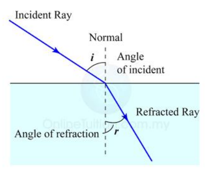
• When light passes through a medium which is denser i > r • When light passes through a medium which is less dense i < r • Snell’s law states that the value of (sin i) / (sin r) is constant for light passing from one given medium into another
\(\frac{sin i}{sin r}\) = constant , n
Here n is the refractive index. Remember that n>1 • Another equation for refractive index is
Refractive index , n = \(\frac{speed \;of\; light\; in\; vacuum}{speed\; of\; light\; in\; medium}= \frac{c}{v}\)
Note: The greater the refractive index, the denser is the medium. Hence, the speed of light in the medium will be slower. • Total internal reflection and the critical angle
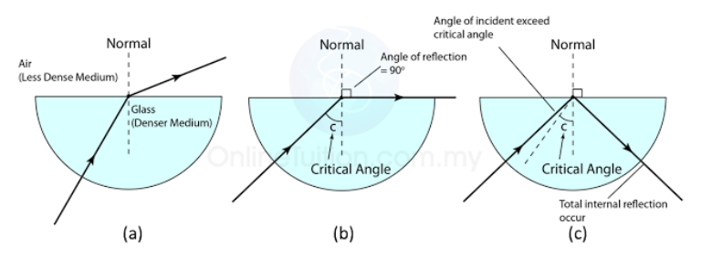
\(n = \frac{1}{sin\;c}\)
Note: The light ray must propagate from an optically denser medium to an optically less dense medium. The angle of incident must exceed the critical angle. • Some phenomenon related to internal reflection and the critical angle 1) Mirage 2) Rainbow
3.2.3 Thin lenses
1. Describe the action of thin converging and thin diverging lenses on a parallel beam of light 2 Define and use the terms focal length, principal axis and principal focus (focal point) 3 Draw and use ray diagrams for the formation of a real image by a converging lens 4 Describe the characteristics of an image using the terms enlarged/same size/diminished, upright/inverted and real/virtual 5. Know that a virtual image is formed when diverging rays are extrapolated backwards and does not form a visible projection on a screen
6. Draw and use ray diagrams for the formation of a virtual image by a converging lens 7. Describe the use of a single lens as a magnifying glass 8. Describe the use of converging and diverging lenses to correct long-sightedness and short- sightedness
3.2.4 Dispersion of light
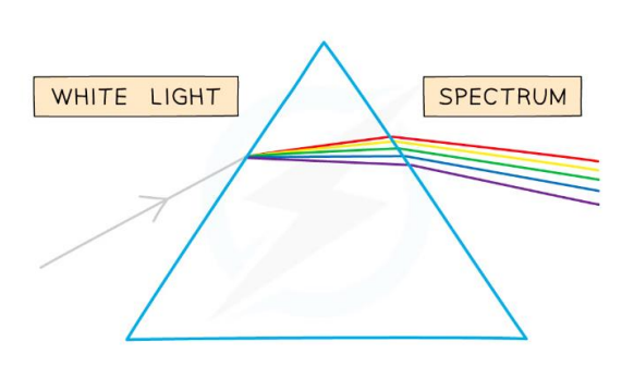
1. Describe the dispersion of light as illustrated by the refraction of white light by a glass prism 2. Know the traditional seven colours of the visible spectrum in order of frequency and in order of wavelength
3. Recall that visible light of a single frequency is described as monochromatic
• For a converging lens (convex lens) , when parallel rays of light pass through a lens, they are brought to focus at a point known as the principal focus (f). • The distance of the principal focus from the lens is called the focal length which depend on the curvature of the lens. • There are three rules for drawing ray diagram for convex lens
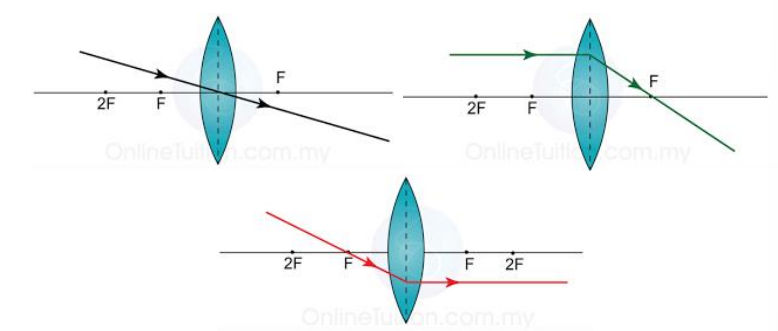
• The characteristics of the image form using a convex lens is always either virtual or real; upright or inverted; magnify or diminish. • DO NOT memorize the characteristics for different object positions. • Try to use the three rules and draw them out!!!!
• When light is refracted by a prism, the incidence ray is not parallel to the emergent ray, since the prism’s sides are not parallel. • If a beam of white light is passed through a prism it is dispersed into a spectrum. • White light is a mixture of colours, and the prism refracts each colour by a different amount – red is deviated the least and violet the most. • The seven colours of the spectrum are red, orange, yellow, green, blue, indigo and violet. • Light is an electromagnetic wave ; hence it is a transverse wave. • Red has the largest wavelength. • Violet has the shortest wavelength. • Light of a single wavelength is known as monochromatic.
3.3 Electromagnetic spectrum
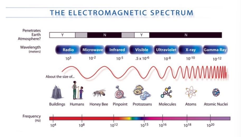
1. Know the main regions of the electromagnetic spectrum in order of frequency and in order of wavelength 2. Know that all electromagnetic waves travel at the same high speed in a vacuum 3. Describe typical uses of the different regions of the electromagnetic spectrum including: (a) radio waves; radio and television transmissions, astronomy, radio frequency identification (RFID)
(b) microwaves; satellite television, mobile phones (cell phones), microwave ovens
(c) infrared; electric grills, short range communications such as remote controllers for televisions, intruder alarms, thermal imaging, optical fibres
(d) visible light; vision, photography, illumination
(e) ultraviolet; security marking, detecting fake bank notes, sterilising water
(f) X-rays; medical scanning, security scanners
(g) gamma rays; sterilising food and medical equipment, detection of cancer and its treatment 4. Describe the harmful effects on people of excessive exposure to electromagnetic radiation, including: (a) microwaves; internal heating of body cells
(b) infrared; skin burns
(c) ultraviolet; damage to surface cells and eyes, leading to skin cancer and eye conditions
(d) X-rays and gamma rays; mutation or damage to cells in the body
6. Know that the speed of electromagnetic waves in a vacuum is \(3.0 \times 10^8\) m/s and is approximately the same in air.
• Electromagnetic waves are transverse waves. • It consists of electric field and magnetic field components. • It can propagate without the need of a medium to carry them unlike mechanical waves. • The speed that electromagnetic waves travel at is \(3\times 10^8 ms^{-1}\) • If this number seems familiar it’s because that’s the speed of light. • Light is a wave or more specifically an electromagnetic wave. • There are seven types of waves in the electromagnetic spectrum as shown below. • Based on the diagram below, frequency (f) increases from left to right. • While wavelength (λ) decreases from left to right. • This is due to v = f x λ • The speed of the wave is constant (v), hence if the frequency (f) decreases the wavelength (λ) must increase to compensate.
5. Know that communication with artificial satellites is mainly by microwaves: (a) some satellite phones use low orbit artificial satellites (b) some satellite phones and direct broadcast satellite television use geostationary satellites
7. Know that many important systems of communications rely on electromagnetic radiation including: (a) mobile phones (cell phones) and wireless internet use microwaves because microwaves can penetrate some walls and only require a short aerial for transmission and reception
(b) Bluetooth uses radio waves because radio waves pass through walls but the signal is weakened on doing so
(c) optical fibres (visible light or infrared) are used for cable television and high-speed broadband because glass is transparent to visible light and some infrared; visible light and short wavelength infrared can carry high rates of data
8. Know the difference between a digital and analogue signal 9. Know that a sound can be transmitted as a digital or analogue signal 10. Explain the benefits of digital signaling including increased rate of transmission of data and increased range due to accurate signal regeneration.
• Electromagnetic radiation is used for communication and transmission of information. • The waves that are used in this way are radio waves (radio), microwaves (mobile phone, Bluetooth and WIFI), infrared radiation (aircon remove control) and visible light (optical fiber). • The method of communication requires the use of a code or signals. • There are two types of signal 1) Analogue 2) Digital
• An analogue signal changes in frequency and amplitude with time. • A digital signal has only 0s and 1s
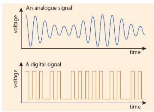
• Digital signals have advantages over analogue signals. • Digital signals have increased capacity, better quality and can be stored and processed by computers. • Increased capacity allow digital signals to carry more information compared to analogue. • Both digital and analogue can pick up unwanted signals that distort the original sound (remember hearing static over radio?) • However, the advantage of digital is that noise in digital signals can be clean up in process known as regeneration because each pulse is 0 or 1 other values can be removed.
1. Describe the production of sound by vibrating sources 2. Describe the longitudinal nature of sound waves 3 State the approximate range of frequencies audible to humans as 20 Hz to 20 000 Hz 4. Know that a medium is needed to transmit sound waves 5. Know that the speed of sound in air is approximately 330-350 m/s 6. Describe a method involving a measurement of distance and time for determining the speed of sound in air 7. Describe how changes in amplitude and frequency affect the loudness and pitch of sound waves 8. Describe an echo as the reflection of sound waves 9. Define ultrasound as sound with a frequency higher than 20 kHz
10. Describe compression and rarefaction 11. Know that, in general, sound travels faster in solids than in liquids and faster in liquids than in gases 12. Describe the uses of ultrasound in non- destructive testing of materials, medical scanning of soft tissue and sonar including calculation of depth or distance from time and wave speed
• Recall that sound waves are longitudinal waves. • Sound waves are mechanical waves as they require a medium to propagate through. • Sound waves travel through solid, liquid and gas by “passing along” the vibration from one particle to the next. • Hence the speed of sound is highest in solids (concrete: 5000m/s) then in liquids (pure water: 1400m/s) and slowest in gases (air: 330m/s)
• The speed of sound can be calculated by using
Speed of sound = \(\frac{𝐷𝑖𝑠𝑡𝑎𝑛𝑐𝑒\; 𝑡𝑟𝑎𝑣𝑒𝑙𝑙𝑒𝑑\; 𝑏𝑦\; 𝑠𝑜𝑢𝑛d}{𝑇𝑖𝑚𝑒 𝑡𝑎𝑘𝑒n}\)
• An echo is produced when sound is reflected of a surface • Pitch is related to the frequency of the sound. • The greater the frequency, the higher the pitch. • Humans can hear between 20 Hz and 20 kHz. • Human vocal range is between 80 Hz to 1100 Hz. • Soprano singers would be in the higher range of frequency while bass singer would be on the lower! • Sound waves less than 20 Hz are known as infrasound while those above 20 kHz are known as ultrasound. • Loudness is related to the amplitude of the sound. The bigger the amplitude the louder the sound.
Measure Waves Experiment: Physics Required Practical
Related Topics: More Lessons for IGCSE Physics Math Worksheets
Waves: GCSE Physics Required Practicals
Observing the properties of waves in liquids and solids.
In this practical you will:
- use a ripple tank to set up waves
- measure the wavelength and frequency of the water waves and use your measurements to calculate the wave speed
- use a vibration generator to set up a stationary wave in a string
- measure the wavelength and frequency of the waves in the string and use your measurements to calculate the wave speed.
Activity 1: Observing water waves in a ripple tank
- Set up the ripple tank as shown in the diagram. Make sure that there is a large sheet of white card or paper on the floor under the tank.
- Pour water to a depth of about 5 mm into the tank.
- Adjust the height of the wooden rod so that it just touches the surface of the water.
- Switch on the overhead lamp and the electric motor.
- Adjust the speed of the motor to produce low frequency water waves.
- Adjust the height of the lamp so that the pattern of the waves can be clearly seen on the white card.
- Place a metre ruler at right angles to the waves shown in the pattern on the card. Measure across as many waves as you can. Then divide that length by the number of waves. This gives the wavelength of the waves. Record this value in the table below.
- Count the number of waves passing a point in the pattern over a given time (say 10 seconds). Then divide the number of waves counted by 10. This gives the frequency of the waves. Record this value in the table below.
- Calculate the speed of the waves using the equation: Wave speed = frequency x wavelength
- Record this value in a table.
Activity 2: Observing waves in a solid
- Set up the apparatus as shown in the diagram.
- Switch on the vibration generator. The string (or elasticated cord) should start to vibrate.
- To see a clear wave pattern, adjust the tension in the string or move the wooden bridge to adjust the length of the string. The waves should look like they are not moving.
- Use a metre ruler to measure across as many half wavelengths as possible (a half wavelength is one loop). Then divide the total length by the number of half waves. Multiplying this number by two will give the wavelength.
- The frequency of the wave is the frequency of the signal generator (power supply).
- Calculate the speed of the wave using the equation: Wave speed = frequency x wavelength
- Repeat steps 2-6 for different frequencies.

We welcome your feedback, comments and questions about this site or page. Please submit your feedback or enquiries via our Feedback page.

GCSE Physics Online
Achieve Your Highest Grade
Home | Premium Plan | Students | Parents | Teachers | Past Papers | Practice Papers | Shop
CCEA
Waves Practical
Waves on a Ripple Tank (measuring Frequency and Wavelength) and RESULTS
The speed of water waves on a ripple tank can be calculated by measuring the frequency (using slow motion footage) and the wavelength (from a photograph).

You may also be interested in...
Click below to return to your exam board
- Misconceptions
- Classroom Physics
Share this article:
Basic experiments with ripple tanks, simple circular pulses in ripple tanks, simple straight pulses, reflection of a straight pulse by a barrier, reflection of a circular pulse by a barrier, reflection at a parabolic barrier, reflection of ripples at a circular barrier.
- Elliptical reflector
Vibrator to generate continuous waves
Introducing the ripple tank, a powerful tool that can help students visualize wave behaviour in general. By pointing out that wavefronts are perpendicular to the direction of motion of the wave, you can link ripple tank experiments to experiments in optics, where rays show the direction of motion of the light.
This is a set of experiments on wave reflections. Students are introduced to ripple tanks and gain confidence in using them, by doing some simple experiments with pulses.
Practical Activity for 14-16

Demonstration
Good questions will encourage close observations of circular pulses in a ripple tank.
Apparatus and Materials
Ripple tank and accessories
- Water Dropper
Health & Safety and Technical Notes
Beware of water on the laboratory floor. Make sure you have a sponge and bucket handy to mop up spills immediately.
Place the power supply for the lamp on a bench, not on the floor by the tank.
Read our standard health & safety guidance

- Start a single ripple somewhere in the middle of the tank and then making several such ripples one after the other. Show this can be done using:
- Pencil to touch the water
- Drop of water from an eye dropper
- What is the shape of the pulse as it travels out?
- Is the speed of travel the same in all directions? How can you tell?
- Is the speed the same near to the centre of the tank and at the edges?
- Is the water moving along with the wave pattern? Drop a scrap of paper onto the water to see if it travels.
- Let students suggest their own tests. Any materials that students suggest for a test can be fetched quickly; and if they suggest none, the problem had best be left unsettled.
Teaching Notes
- Possible learning outcomes from this experiment:
- Students become more familiar with the ripple tank.
- They find that the water does not move out with the ripple.
- They learn what is meant by a circular ripple.
- They deduce that it is circular because – if the water is of constant depth – the disturbance travels with the same speed in all directions.
- They might deduce what happens to the ripple speed if the water depth increases.
- Pulses will be circular if the tank is level. A circular wave train demonstrates that waves travel the same distance in the same time.
This experiment was safety-tested in February 2006
Observing what happens when straight wave pulses are produced in a ripple tank.
For each group of students
Ripple tank accessories

- Lay the rod in the tank and produce a pulse by giving it a tiny but sharp roll forwards and back (see diagram}. You may find that it is sufficient just to tap the rod. You can produce continuous waves by repeating this motion periodically.
- Ask: Do the ripples change as they move away from the rod? If so, how?
- Students should observe that the ripples are rather wide near the rod but become sharper as they move away.
- The ripples are sharpest when the filament of the lamp is parallel to them. (This is why special 48 W lamps are required.)
This ripple tank experiment provides a good introduction to wave reflections. Students will see a pattern in the reflections more clearly with a simple straight pulse than they might with continuous straight ripples.
For each group of students:
- Barrier, straight
Read our standard health & safety guidance

- Ask: 'Can you see any simple story about the direction of straight waves before and after meeting a flat wall? How are the angles related?'
- Do not, at this stage, talk about laws of reflection, measurements of angles, or urge students to remember what they saw before.
- Make a straight-line pulse and watch what happens when it hits a straight reflecting barrier. It is easier to see what happens when there is a single pulse rather than a series of waves.
- Try directing a pulse head-on (normally) to the barrier and then at various other angles, larger or smaller than 45°. Avoid just 45° because this produces a grid pattern and it is hard to tell the difference between incident and reflected rays.
- Most students will bring out some story about angles. It does not matter at all whether the angles are angles between wavefront and barrier or wavefront and the normal. Dragging in references to the normal in these simple studies of reflection is no help at all. Even with a curved reflector, young people can imagine a tangent to the surface just as easily as they imagine a normal. All you want here is some idea of ' equal angles'.
- At this point students could be introduced to ‘rays’ as guide lines indicating the direction in which the wave is travelling. Place a metre rule at right angles to the wave fronts to help students to ‘see’ where the rays are. This would link ripple tank experiments to ray optics.
- The template with two sets of parallel lines can be used with an OHT to simulate reflection and interference of plane waves, at a straight barrier.
Download template
You can use a ripple tank to introduce ideas about the relationship between an ‘object’ and its mirror ‘image’.
For each student group
- Straight barrier
- Water dropper
You can use either a water dropper or a pencil (dipped in the surface of the water).

- Ask: ‘When a circular ripple (pulse} is bounced back by a straight wall, where does the wave seem to come from after that?' Do not give the answer to that, and do not, at this stage, discuss images. Instead, ask students to carefully observe this process in their ripple tanks.
- Tell them to place the barrier somewhere near the middle of the tank (so that the image from which the reflected ripple seems to come is well inside the tank).
- When students have seen this for themselves, suggest some further experiments:
- 'Now that you know where the ripple that bounces back seems to come from, try starting a ripple just there. Use the finger of one hand. Let the ripple spread and hit the wall and bounce back. Mark the place where the bounced back ripple seems to come from, with a finger of your other hand.'
- Then start a ripple from that place with that finger.
- 'Now start ripples with both those fingers at the same moment. Watch what happens'
- When that succeeds, it is amusing and almost uncanny. Students may notice the geometry, but it will not matter if they fail to notice it. The main aim here is to emphasize the idea of a ' place from which the reflected wave seems to come'.
- Do not spoil the fun by doing it for students even though you can probably make the simultaneous ripples (the incident ripple and the image ripple) much more easily. Do, however, help students who are unsuccessful by encouraging them to put the second finger at the right place - without using the word image or giving the geometry. Just judge the right distance with your own eyes and point to the right place. Then the student can try again, see success and enjoy it.
- Students who find it difficult to remember the position of the place the reflected ripple comes from (the image) could put a small coin in the tank at that spot. More able students could measure the distances of the ‘object’ and ‘image’ from the barrier after marking their positions.
This experiment was safety-tested in May 2006
Students may have done some ray optics with light using parabolic reflectors such as those in the back of car headlights. This ripple tank experiment helps to show how a parallel beam is produced.
- Copper wire, heavy
- Rubber tube, heavy
The parabolic reflector can be made with rubber tubing. To help curve and anchor the tube, put heavy copper wire (or solder) into the tube before bending.

- First ask, 'What happens to straight line waves when they hit a parabolic reflecting wall?’
- Whether or not students have done so before, get them to try this.
- Then ask, ‘Can you turn that story backwards and make straight line waves come out from the wall?'
- This is an exercise in thinking as a scientist, so we should be very careful not to reduce it to an exercise in carrying out instructions. Simply ask the question about the reverse effect.
- Students may have done some ray optics with light, using parabolic reflectors such as those in the back of car headlights. This experiment will help to show how a parallel beam is produced
- They should find the wave concentrated after reflection into a circular ripple which closed down to a small size and then spread out again.
- After students have seen the straight line ripple reflected into a circular ripple that moves to a point, they should know where to put their finger to start the reverse experiment.
This experiment is best done after students have used a ripple tank to experiment with a pulse reflected by both straight and parabolic barriers.
- Barrier, semi-circular

Ask students to try any experiments they like, using a circular barrier.
- Do not tell students to start a circular pulse from the centre of the reflector (but many will do that of their own accord). Do not tell them to find the place where straight pulses are brought to a point after reflection; and certainly do not ask them to measure that distance and see whether it is half the radius of the mirror. It is much better to leave students to their own experimenting.
- A ripple started at the centre of curvature of the barrier will return to the same point. A circular ripple started half way between the centre of the circular barrier and the barrier itself will produce a parallel beam. The connection with ray optics is clear.
- For very able students only – you might want to:
- discuss the geometry and ask students to locate a 'focus',
- ask students to turn the reflector round and use it as a convex reflector, and look for virtual image effects.
This experiment was safety-checked in February 2006
A circular pulse started at one focus will be reflected as a straight pulse from the nearest part of the elliptical barrier. The straight pulse will then travel to the farthest part of the barrier to be reflected as a circular pulse centred on the second focus.
The beauty of this demonstration is very sensitive to the accuracy of the ellipse. Some manufacturers supply such an elliptical reflector in the ripple tank kit as an optional extra.
To be sure of the necessary accuracy, you may prefer to make your own barrier. First draw an ellipse very carefully on paper. Someone skilful can then bend a springy brass strip to fit the ellipse, joining the ends with a butt joint and a strap outside. (This type needs very careful storage.)
Alternatively, you can draw the ellipse on plywood and then cut it out to the required shape. Great care must be taken if this method is used.
To make the best reflector of all, use a wall of plaster of Paris, drawing the ellipse with a peg moving along a loop of wire.
Coating the reflector with paraffin wax may improve the regularity of reflection by making an angle of contact with the walls exactly 90°.
- Place the elliptical reflector in the middle of a ripple tank with very clean water. Start a single ripple accurately at one focus and watch its progress.
- The position of one focus of the ellipse must be located very accurately and used as the starting point of the ripples. Perhaps the best way of finding the focus is trial by ripples . Then place two small coins in the tank to mark the two focuses.
- This is an intriguing ripple tank experiment to watch. Image formation by a wide-aperture reflector like this depends on the wave path being the same from object to image by all routes, even those that use extreme portions of the aperture. An ellipse does this - though it fails to give a good image of points a little way off the focus.
- However, if part of the reflecting surface is a little off the true ellipse, the condition fails and reflection there may even harm the image instead of helping to form it. An error of 1/4 wavelength in part of the surface will do great harm. Considering how small the actual wavelength of the equivalent ripples in a pulse must be, this error is very small.
Some ripple tank experiments previously done with wave pulses can be repeated with continuous waves, either plane or circular. Continuous straight waves are also used in other experiment collections in the Waves topic.
- Motor mounted on beam, with beam support
- Rubber bands, 2
- Leads, one set, to motor
- Dry cells, 2
Power for the motor:
The motor works well from a 1.5 volt cell in series with a 12-ohm rheostat. Two cells may be needed for the higher speeds but the motor then goes rather fast with the rheostat set at its minimum value. The polarity of the battery determines the direction of rotation, but that is immaterial. (If a battery with a higher e.m.f. is used, a rheostat with a correspondingly high resistance would be required.)
Some manufacturers supply special power units for use with the ripple tanks. These provide the necessary voltage for the lamps and also a variable voltage output to drive the motors. They avoid the need for a transformer to light the lamp and a separate supply for the motors and some teachers may prefer to use them despite the extra cost.

- Take the wooden beam with the motor attached and hang it by two rubber bands of such length that the wood is above the water.
- Attach a small spherical dipper to the vibrator by its L-shaped rod and adjust it so that the bottom of the sphere is about level with the surface of the water.
- At low frequencies, it is easy to see the waves; but at higher frequencies the persistence of vision obscures them. Blinking makes them visible.
- Remove the dipper and re-adjust the height of the wooden beam so that the beam itself is about level with the surface of the water. When the beam is set vibrating, straight waves will travel across the ripple tank. If the beam is too deep in the water (or sitting on its glass bottom!) the ripples do not travel very far; if it is too shallow and the vibration is vigorous, the ripples are less distinct near the vibrator.
- You will find that some experiments are best done with pulses only, as the reflections from continuous waves produce confusing patterns.
- For best results, the filament of the lamp should be parallel to the ripples.
- If the wooden rod does not vibrate enough, increase the eccentric loading on the shaft of the motor.
Support our manifesto for change
The IOP wants to support young people to fulfil their potential by doing physics. Please sign the manifesto today so that we can show our politicians there is widespread support for improving equity and inclusion across the education sector.
Physics Links Explorer
0625_RP_Videos
Topic outline.
- Select activity Each experiment is accompanied by a Teaching Pack ... Each experiment is accompanied by a Teaching Pack which includes lesson plans, worksheets and teacher guidance. There are three videos and a quiz accompanying each pack. This includes a full video, interactive version and virtual experiment.
Available experiments
- Mailing List
- Terms and Conditions
- © Copyright Notice
- International
- Education Jobs
- Schools directory
- Resources Education Jobs Schools directory News Search

AQA Physics Required Practical - Ripple Tank
Subject: Physics
Age range: 14-16
Resource type: Lesson (complete)
Last updated
27 April 2020
- Share through email
- Share through twitter
- Share through linkedin
- Share through facebook
- Share through pinterest

A powerpoint and videos for the AQA GCSE Physics required practical on the ripple tank. Videos included in the powerpoint and also separately. Only download the videos if you need to as the file size is quite large. Questions and answers included. One example also included. Delete slides as appropriate.
Creative Commons "Sharealike"
Your rating is required to reflect your happiness.
It's good to leave some feedback.
Something went wrong, please try again later.
Fantastic resource! Great for helping my Y11s understand the different aspects of the ripple tank required practical, thank you for sharing this for free.
Empty reply does not make any sense for the end user
susanhalsall
clear and easy to follow. Broken down into clear tasks for students
Just what I needed. Thank you.
Laura_d_chapman
This is so helpful, thank you for sharing.
Fabulous resource. Worked examples and a video that carries out the practical inside the PPT. Pretty boring lesson/demo to do normally. This is fantastic
Report this resource to let us know if it violates our terms and conditions. Our customer service team will review your report and will be in touch.
Not quite what you were looking for? Search by keyword to find the right resource:
- UK GCSE (Age 14-16)
- UK A-level (Age 16-18)
- UK Higher Ed. (Age 18+)
Tensile Testing (lite)

Structural materials are required to withstand a variety of applied loads in use. Understanding how these materials respond to applied loads is vital for informed materials selection. Here you can investigate how materials behave under tensile loading (loads applied along the length of a material to cause stretching).
This is only the LITE version, the full version (wtih all materials) is availabe via log-in. Press GO to launch the experiment!
- Application
- Quick Guide
- Full Instructions
What is ‘Tensile Testing’?
The ‘tensile’ properties of a material describe its most basic mechanical behaviour – how much does a material stretch when it is pulled and how much of the stretching is permanent? ‘Tensile Testing’ is the process of measuring a material’s tensile properties.
Why are tensile properties important?
Understanding of tensile properties is vital for any application that uses materials structurally, i.e. to withstand or apply force. The range of uses this covers is enormous. Strong and stiff structures are used in vehicles (cycles, cars, trains, aeroplanes, spacecraft), bridges and buildings, sports equipment and bio-implants (e.g. hip joint replacements). Flexible materials are also used in many of these applications. Thin but robust materials are used in touchscreens. Hard materials are used in machines and robots that process and shape other materials and as durable coatings that improve the performance and lifetime of aerospace and bio-implant components. Elastic materials can be stretched enormously before any permanent change is made and are used in springs and high performance fabrics. And it’s not just how a component is used – many manufacturing processes involve changing a component’s shape or response to applied forces, e.g. extrusion to make tubes, beams and bottles; drawing to make springs or wires; or forging and rolling to shape and harden metals.
Use this experiment to find out more!
Download the file below for the quick guide for the Tensile Testing experiment (requires login) or follow these brief instructions:
To select a sample:
- Click the lower jaw to go to the sample view.
- Open the calliper jaws, drag a sample of choice between the jaw and fully close the jaws around it. (In this LITE version you can only select one of the samples).
- Use the Vernier scale to measure the sample width.
- Click the sample held in the callipers to use it in the tensile testing machine.
- Or open the callipers, return the sample to its original position and choose another sample. (Only available in the full version).
To set the strain increment:
- Click the Set button (display starts to flash).
- Use the keypad and the Del button to enter the desired Step value.
- Click the Set button again (display stops flashing).
To apply strain to samples:
- Set the strain increment value as described above.
- Click the up arrow to increase the applied strain by the Step increment value.
- Click the down arrow to decrease the applied strain by the Step increment value.
- Measure (and record) the applied load (force) using the needles on the Load dial.
- Turn off the strain control unit and click on the lower sample holder to select a new sample.
Download the file below for full instructions for the Tensile Testing experiment (requires login).
Structural materials are required to withstand a variety of applied loads in use. Understanding how these materials respond to the applied loads is vital for informed materials selection. Here we investigate how materials behave under tensile loading (loads applied along the length of a material to cause stretching).
The Tensile Test experiment allows a number of mechanical tests to be performed on materials, including:
- Determination of full stress-strain curve to fracture, using either ‘engineering’ or ‘true’ value
- Observation of elastic behaviour and calculation of Young’s modulus
- Observation of the onset of plastic behaviour and permanent deformation
- Calculation of moduli of resilience and toughness
- Calculation of strain energy in a system
- Calculation of work done in deforming a sample
Download the file below for activities for the Tensile Testing experiment (requires login).
- QUICK ACTIVITIES: 9 quick activities to try
- ACTIVITY 1: Elastic deformation
- ACTIVITY 2: Plastic deformation
- ACTIVITY 3: Fracture
(Available as separate downloads or all activities)
*NEW* Now also available in editable Microsoft Word format
We have also provided a spreadsheet file to allow you to enter your SAMPLE WIDTH, STRAIN and APPLIED LOAD data and obtain stress-strain plots. (HINT: to investigate the general form of stress-strain curves with younger students, use a default sample width of, say, 7 mm)
Watch the video above and download the file below for the background science behind the Tensile Testing experiment (requires log in).
Ohm's Law

Ohm's law is a fundamental equation that shows how voltage, electrical current and electrical resistance are related in simple conductors such as resistors. This experiments allows you to explore Ohm's law and how the coloured bands on resistors codes their resistance. In doing this you will also learn how to use a power supply and 'digital multimeters'.
Press GO to launch the experiment!
Ohm’s law
Voltage , current and resistance are the most fundamental quantities for describing the flow of electricity . Ohm’s law shows how these three quantities are related and so is a powerful way of understanding the basic nature of electricity.
This is relevant to vast areas of technology today, including national electricity grids, power generation, design of all electronic devices and all electronic circuits, heating, electrical safety and understanding of natural phenomena such as lightning. This experiment will allow you to explore Ohm’s law by making measurements of voltage, current and resistance.
Resistors are the simplest and most commonly used electronic component and almost all electronic circuits contain them. They can be used to change the properties of any circuit they are part of, such as current flow , how voltage is distributed across components, the speed of a circuit , the amount of amplification from a circuit, the response of a sensor or the amount of electrical heating from a circuit.
The simplest resistors are made of a thin film or wound wire of carbon or metal . They usually have a series of coloured bands that represents both their target resistance value and how much the actual value might vary from this (the ‘ tolerance ’). This experiment lets you practise selecting the appropriate colour bands on a resistor to achieve a certain resistance value.
Digital Multimeters
Digital multimeters (DMMs) are versatile pieces of equipment commonly found in electronics, physics and engineering labs. In this experiment you’ll learn how to use a DMM to measure voltage , current and resistance . You’ll see this piece of equipment in many other FlashyScience experiments!
Download the file below for the quick guide for the Ohm's Law experiment (requires login) or follow these brief instructions:
To measure resistance:
- On the right-hand Digital Multimeter (DMM), rotate the switch to resistance measurement.
- Click and drag the clips on the wires attached to the right-hand DMM so that they snap to the wires either side of the resistor (make sure the power supply is turned off).
- Note the resistance value shown on the DMM screen.
To change the resistor:
- Click the resistor you wish to change to move to the Selection screen.
- Click on the colour band you wish to change.
- Click on the palette colour you wish to select.
- Click on the resistor wire to return to the main screen.
To use voltage and current:
- Turn on the power supply (right hand side of screen) and turn the dial to set the voltage.
- To measure current through the resistor – turn the left-hand DMM dial to DC current.
- To measure the voltage across the resistor – turn the right-hand DMM dial to DC voltage.
- NOTE: in this experiment the power supply voltage is also shown directly on its display.
Download the file below for full instructions for the Ohm's Law experiment (requires log in).
Download the files below for activities for the Ohm's Law experiment (requires login).
- ACTIVITY 1: Investigate what the different coloured bands on resistors mean
- ACTIVITY 2: Learn how to use a DMM to measure electrical resistance
- ACTIVITY 3: Explore the effect of the tolerance band (band 4) on resistors
- ACTIVITY 4: Explore the statistics of resistance values from resistors with the same band colour coding
- ACTIVITY 5: Investigate Ohm’s law by measurement of voltage and current with a resistor
- ACTIVITY 6: Investigate Ohm’s law by measurement of current for different resistors with a fixed voltage
- ACTIVITY 7: Investigate Ohm’s law by measurement of voltage for different resistors with a constant current
- ACTIVITY 8: Investigate the power consumption due to electricity flowing in a single resistor
- ACTIVITY 9: Investigate the power consumption due to electricity flowing through different resistances
Download the file below for the background science behind the Ohm's Law experiment (requires log in).
Free-fall due to Gravity

Gravity is a fundamental force in nature, without which we would not have galaxies, stars, the Earth, oceans, life on Earth... or golf. This experiment allows you to measure the acceleration due to gravity by measuring the time taken for a ball to fall through different heights. You can choose between two ways of timing the free fall, and you can even travel through space to measure the strength of gravity on different objects of the Solar system!
It is safe to say that gravity is important to us! Without gravity there would be no life on Earth and, in fact, without gravity, the Earth would never have existed.
Gravity is responsible for stars forming in the first place, keeping the Sun from exploding from the heat it generates, and for the structure of galaxies. It also keeps the Earth in orbit around the Sun, keeps our atmosphere and oceans in place and means we don’t float off into space. Gravity even allows plants to detect which way is ‘up’ so they send their roots and shoots in the right directions. You can see more at this NASA web page .
So, why does it matter that we know how strong gravity is?
Well, for lots of reasons.
The strength of gravity is essential to know in Civil Engineering projects such as design of buildings and bridges so we can calculate the stresses materials are under .
Aircraft and space rocket designers must know the strength of gravity that must be overcome and satellite technology is based upon a certain strength of gravity to maintain orbits at particular heights above the Earth.
Hydroelectric power generation also relies on gravitational potential energy, either through energy ‘storage’ in dams or from the water flow or tides in rivers or oceans.
Our quality of life would be very different too. Most sports rely on gravity (we’re not counting chess as a sport here!) and gravity even keeps food in a saucepan while it cooks!
Download the file below for the quick guide for the Free-fall due to Gravity experiment (requires login) or follow these brief instructions:
- Choose between using a Pressure Pad sensor and Light Gate sensors using switch on side of timer.
- Click and drag the electromagnet
- Read the height of the ball on the electromagnet using the magnified view of the ruler
- Press the Start/Reset button to release the ball from the electromagnet
- Read the time (from the timer) for the ball to drop to the pressure pad
- Press the Start/Reset button to return the ball to the electromagnet and reset the timer to zero
- Click and drag the electromagnet and both light gates to adjust their height on the ruler but ensure the separation of the electromagnet and first light gate is constant throughout your experiment
- Measure the distance between light gates using the magnified view of the ruler
- Read the time for the ball to fall between the light gates
Measured Earth’s gravity? Click on the poster to explore gravity elsewhere in the Solar System too!
Download the file below for full instructions for the Free-fall due to Gravity experiment (requires log in).
Download the files below for activities for the Free-fall due to Gravity experiment (requires login).
- ACTIVITY 1: Measurement of g using pressure pad sensor
- ACTIVITY 2: Measurement of g using light gate sensors
- ACTIVITY 3: Travel the Solar System!
- ACTIVITY 4: Uncertainty in g based on uncertainty in individual measurement
Download the file below for the background science behind the Free-fall due to Gravity experiment (requires log in).
Radioactivity

Radioactive materials are used by us in lots of ways. This experiment allows you to explore alpha, beta and gamma radiation and how they are absorbed by various materials. You can also measure the change in radioactive signal with distance from the radiation source and even time travel to measure the halflife of radioactive decay for different elements!
Radioactive elements (radionuclides or radioactive isotopes) produce high energy particles and are used in a huge range of applications. Most people know about nuclear power , which converts the energy of radiation from uranium-238 or plutonium-239 into heat and then electrical power, even in small-scale form for remote applications (e.g. spacecraft). There are far more widespread uses all around us though.
Radionuclides are used in many medicinal applications . They can be used as tracers to follow fluid flow inside the body by detecting the radionuclide emitted radiation (e.g. technetium-99, thallium-201, iodine-131 and sodium-24). Medical imaging can use radioactive elements that naturally collect in particular parts of the body and image the radioactive emission. For example, iodine-131 is used to image the thyroid and other isotopes can be used for other organs, such as bones, heart, liver and lungs. Larger doses of the radionuclides (e.g. cobalt-60) are used to create a targeted radiotherapy treatment of cancer in these organs. It is even possible to detect the presence of Heliobacter pylori (an unwanted bacterium that can be in stomachs) with a simple breath test that uses carbon-14.
You may have radioactive materials in your home, school or workplace. Smoke detectors use alpha radiation from americium-241 to ionise smoke particles for detection. Glow-in-the-dark inks on clocks, watches and emergency signs that convert radioactive particle energy from promethium-147 into light.
You may also have food that has been treated with radiation. Many foods (including tomatoes, mushrooms, berries, cereals, eggs, fish and some meat products) are irradiated with gamma rays from cobalt-60 to kill micro-organisms and improve the food’s shelf life (without making the food radioactive!). Similarly, gamma radiation from caesium-137 is used to sterilise medical products such as syringes, heart valves, surgical instruments and contact lens solutions.
Radioactive elements are used in industry too. For example, the absorption of different types of radiation mean it can be used to monitor the thickness of manufactured components and sheets. Radionuclides are also used for detecting leaks from pipes , the direction of underground pipes and waste dispersal in the environment. Radioactive sources are also used in industrial imaging , with the sample placed between the radiation source and a detector. Certain isotopes are used as chemicals in order to trace chemical reaction routes , e.g. carbon-14 in photosynthesis. Similar approaches are used in biology to test when proteins undergo important ‘ phosphorylation ’ reactions (using phosphorus-32) to learn when their function is activated by other proteins or small chemicals.
Radioactive elements can also be used for historical dating of objects, e.g. carbon-14 dating for estimating the age of organic matter and uranium-238 for rocks. Similarly, radioactive decay from vintage drinks such as wine can be used to prove their age, since radionuclides were released into the atmosphere by nuclear explosion tests after World War II and are present in all food and drink produced since then.
With so many uses, it’s no wonder that radioactive decay is an important aspect of science and engineering!
Download the file below for the quick guide for the Radioactivity experiment (requires login) or follow these brief instructions:
Select the radiation source:
- Click on the Source holder.
- Click on one of the radiation sources in the tray and then in the holder.
Detecting radiation:
- Click the power switch on the Geiger-Müller counter .
- Read the needle position on the dial to measure level of radiation.
Changing the filter material and thickness:
- Click on the filter holder.
- Click on the material of choice to increase its thickness in the holder by 1 mm.
- Click on the material in the holder to reduce its thickness by 1 mm.
- Measure the filter thickness using the markings inside the holder.
Change the source-detector separation:
- Click and drag the holder mount to move it along the ruler.
- Measure the mount’s position using the magnified ruler view seen while clicked on the holder mount.
Time travel!
- Move time forward by one minute, hour, day, month or year by clicking on the appropriate value on the clock .
Download the file below for full instructions for the Radioactivity experiment (requires log in).
Download the file below for activities for the Radioactivity experiment (requires login).
- ACTIVITY 1: Radioactive half-life… and time travel! (used in GCSE Physics)
- ACTIVITY 2: Inverse square law (used in A-level Physics)
- ACTIVITY 3: Which materials absorb different types of radiation?
- ACTIVITY 4: Radiation absorption strength
- ACTIVITY 5: Alpha radiation (advanced experiment)
- ACTIVITY 6: Mixed radiation sources
Or see if you can do some of the following:
- Measure the half-life of different sources (GCSE)
- Measure how detected gamma radiation varies with source-detector separation
- Find out how alpha, beta and gamma radiation is absorbed by various materials
- Explore multi-decay type radioactive sources
Download the file below for the background science behind the Radioactivity experiment (requires log in).
Resistivity of a Wire

The electrical resistivity of a wire tells us how well the wire material conducts electricity. This is crucial information for any application that involves conducting electricity, including wind turbines, electric vehicles, household electrical goods and computers. Here you can measure the resistivity of wires of different materials and widths, and consider which would be best suited for conducting electricity.
Electronic materials are crucial to our life today , and electrical ‘resistivity’ tells us how good or poor a material is at conducting electricity.
We use materials with low electrical resistivity to transmit electrical power from generators, across grid distribution networks , and to homes and workplaces for use . Designers of electrical devices rely on knowing the resistivity of wire used in order to calculate the resistance of components.
These devices range in size from enormous machines such as wind turbines or industrial lifting equipment ; motors or engines in electric vehicles and all-new electric aircraft ; consumer products such as washing machines, hair dryers and ovens ; and the nanoscale components within the computer chips found in smart devices, laptops, and mobile phones .
In fact, modern computing is based on controlling the resistivity of semiconductor materials in a type of transistor (known as ‘field effect transistors’ using ‘CMOS’ technology).
Measuring electrical resistivity helps us to understand the properties of materials, to monitor manufacturing processes, and to select the best material for an application.
Download the file below for the quick guide for the Resistivity of a Wire experiment (requires login) or follow these brief instructions:
- Click on the right hand wire post to move to the Select Wire screen.
- Open the micrometer by dragging the thumbwheel down.
- Choose a material and drag the unlabelled wire into the micrometer.
- Close the micrometer and measure the wire's width.
- Click on the wire while it's in the micrometer to return to the main screen .
- Click on the switch to turn it on.
- Measure voltage and current for a variety of contact positions on the wire.
- Calculate resistance for each contact position.
- Plot resistance vs contact position and calculate the gradient of a line of best fit.
- Multiply the line's gradient by the wire's cross-sectional area to obtain the wire's electrical resistivity.
Download the file below for full instructions for the Resistivity of a Wire experiment (requires log in).
Download the file below for activities for the Resitivity of a Wire experiment (requires login).
- QUICK ACTIVITIES: 5 quick activities to try
- ACTIVITY 1: Different wire lengths
(Available as separate downloads or all activities)
Download the file below for the background science behind the Resitivity of a Wire experiment (requires log in).
Hooke's Law

Hooke's law describes how springs respond to having forces applied. This experiment allows you to apply force using weights and measure how springs of different stiffness extend in response. You can calculate the stored elastic potential energy in the springs and even go to different parts of the Solar System to see how changing the strength of gravity changes the weight applied to the springs!
Stretching – the truth!
You may wonder why we study springs and why questions about stretching springs appear on exams. Sure, springs are used in the world, but are they really so important? Why is it important to know how springs stretch when they are pulled?
Well, first, springs are incredibly useful . When made from elastic materials, such as most metals, springs stretch when pulled and return to their original size when released . They can also be compressed and, again, return to their original size when released. The stretching or compression stores energy that is then returned when the spring is released. This energy storage and return is the key reason springs are useful. Springs use this capability in all sorts of applications, including in high tech areas such as automotive, industrial tools and robotics, to more everyday items such as trampolines, mattresses, children’s play equipment, door handles and retractable pens.
The second reason is that the way that springs respond to force being applied to them (i.e. being pulled or mass added to one end of them) is identical to how materials in general behave. If materials are pulled, then they stretch. The coiled shape of a spring, though, means that the ends tend to move large distances compared to a regular shape of the same material (e.g. a simple rod). This means that studying what happens to springs when they are pulled allows simple measurements to be performed that give us understanding of how all materials behave when they are pulled. Materials behave this way in any application where they have force applied to them, e.g. in construction, vehicles, heart valves, body implants, plants, rocks, furniture, tools, footwear – the list goes on and on. And don’t forget this includes your body too!
Download the file below for the quick guide for the Hooke's Law experiment (requires login) or follow these brief instructions:
- Click on 50 g or 100 g masses to add them to the mass holder.
- Click on the ruler to go to a zoomed view (centimetre scale).
- Click on the masses on the holder to move them back to their boxes.
- To change to a different spring:
- Remove all mass from the holder.
- Click on the spring.
- Select from Low, Medium, High or Unknown Stiffness.
- Click again on the spring to return to main screen.
5. To change to a different part of the Solar System:
- Click on the poster to choose where to do the experiment.
6. Click the Information button to see the controls.
Use this experiment to:
- Test Hooke’s law.
- Measure spring constants.
- Test the ‘limit of proportionality’ for springs.
- Calculate the stored energy of a spring.
- See how different strengths of gravity affect the weight added to a spring.
Download the file below for full instructions for the Hooke's Law experiment (requires log in).
Download the files below for activities and associated worksheets for the Hooke's Law experiment (requires login).
- ACTIVITY 1: Testing Hooke’s law
- ACTIVITY 2: Measurement of the stiffness of a spring
- ACTIVITY 3: Energy stored in a spring
- ACTIVITY 4: Limit of proportionality of a spring
- ACTIVITY 5: Travel the Solar System!
Download the file below for the background science behind the Hooke's Law experiment (requires log in).
Specific Heat Capacity: Solids

Specific heat capacity of solids is important to understand in lots of applications that deal with heat energy and changes in temperature. This experiment allows you to control the electrical heating power applied to a choice of six different materials and measure the rate at which the sample temperature changes. You can then calculate the specific heat capacity of the chosen material. Compare the different materials, investigate the effect of having thermally insulated or uninsulated samples, and see if different heating powers change the measurements.
There are lots of ways that we use materials that see them change temperature. Some examples include heating systems in buildings (especially storage heaters ), simple household appliances such as an iron or an oven , combustion engines in cars, jet engines in aircraft, high speed machines such as drills, and industrial furnaces ; however, examples also include applications where the temperature is reduced, for example in refrigerators , freezers and heat sinks , which are used to help cool another component.
A change in a material’s temperature will also result in a change in its heat energy . Different materials, however, will have a different change in heat energy for a given change in temperature.
The material's property we use to show this difference is called specific heat capacity . This property is key to allowing us to understand how components will perform in thermal applications and help us to choose the most appropriate material. If you go to study Physics or Engineering at university you will probably also learn how specific heat capacity values depend on a material’s types of atom, atomic bonding and electrical properties.
Download the file below for the quick guide for the Specific Heat Capacity: Solids experiment (requires login).
Download the file below for full instructions for the Specific Heat Capacity: Solids experiment (requires log in).
Download the files below for activities and associated worksheets for the Specific Heat Capacity: Solids experiment (requires login).
- ACTIVITY 1: Measurement of specific heat capacity of a material
- ACTIVITY 2: Comparison of specific heat capacity for different materials
- ACTIVITY 3: Measurement of specific heat capacity using different heating powers
- ACTIVITY 4: Effect of insulation on measuring specific heat capacity
(Available as separate downloads or all activities/all worksheets)
Download the file below for the background science behind the Specific Heat Capacity: Solids experiment (requires log in).
Acceleration and Force

Understanding the relationship between force, acceleration and mass is key to starting to understand the physics of changing motion. This experiment allows you to change the mass of a tabletop car and the force applied to it before timing how long it takes the car to move various distances. Analysis of your results will allow you to see the relationship between acceleration and force.
The FlashyScience Acceleration and Force experiment might use a toy car on a table top but the science you can learn from it helps us to understand the world around us, to design all sorts of new vehicles and machines, and even to understand our bodies better.
At the largest of scales, knowing the huge forces involved with galaxies, stars and planets show us how these huge objects move and even how they form. We use our knowledge of force and acceleration to launch objects into space using rockets and to put satellites into stable orbits. This knowledge also allows us to calculate the acceleration of high performance cars (e.g. F1 cars) and aircraft , to design and build machines with moving parts, and to understand the forces parts of our bodies experience through an area of science called biomechanics . Force and acceleration can even be used to measure the mass of atoms and molecules through scientific techniques called mass spectrometry , and help us to understand how atoms interact in gases.
You can see that knowledge of force and acceleration is essential to lots of areas of science, engineering and our lives in general.
Download the file below for the quick guide for the Acceleration and Force experiment (requires login).
Download the file below for full instructions for the Acceleration and Force experiment (requires log in).
Download the files below for activities and associated worksheets for the Acceleration and Force experiment (requires login).
- ACTIVITY 1: Investigating acceleration, F = ma (mass transfer between car and mass holder)
- ACTIVITY 2: Investigating acceleration, F = ma (constant holder mass, increasing car mass)
- ACTIVITY 3: Distance versus time graphs
Download the file below for the background science behind the Acceleration and Force experiment (requires log in).
Density of Solids & Liquids

Density is an 'intrinsic' property of materials and liquids, which means its value doesn't change when the amount of material or liquid changes. This experiment allows you to find the density of various materials with regular and irregular shapes, as well as several liquids, using three methods of determining mass and volume.
Density is a basic property of materials and liquids. It is important in all sorts of areas of science , engineering and medicine . Density (mass per unit volume) is related to the type of atoms within the material or liquid and how they are arranged . Changing the temperature of a solid or liquid often changes its volume , which also changes its density . Different processing treatments of materials can lock in some of these changes, resulting in materials made of the same atoms but with different densities. Many materials can be ‘ porous ’ (contain lots of holes) and being able to measure density is a simple way of finding the level of porosity of a material.
The buoyancy of a solid in a liquid depends upon the density of the solid and liquid. Ice floats in liquid water because ice molecules are more widely spaced than those in water, and so the density of ice is lower than that of water.
The density of solids and liquids is also related to a substance’s refractive index and how it interacts with X-rays. For example, your bones are denser than your muscle tissue and so absorb X-rays more; this allows medical images to be created that show the different regions inside your body.
Density is vital to the efficient design of physical objects, particularly for structural and transport applications. There is a huge demand for engineers and materials scientists to create lighter vehicles and aircraft to reduce their power requirements and help reduce our use of fossil fuels .
Download the file below for the quick guide for the Density of Solids & Liquids experiment (requires login).
Download the file below for full instructions for the Density of Solids & Liquids experiment (requires log in).
Download the files below for activities and associated worksheets for the Density of Solids & Liquids experiment (requires login).
- ACTIVITY 1: Density of regularly shaped objects – cubes and rectangular cuboids
- ACTIVITY 2: Density of regularly shaped objects – spheres
- ACTIVITY 3: Density of irregularly shaped objects
- ACTIVITY 4: Density of liquids
Download the file below for the background science behind the Density of Solids & Liquids experiment (requires log in).
Thermal Insulation

Heat is transmitted by conduction, convection or radiation. This experimental allows you to investigate thermal conduction by measuring the time for thermal energy to pass through different materials.
The thermal conductivity of materials is hugely important for how we live today.
Thermally-insulating materials are found in lots of places around the home. This includes safety items such as oven gloves or fire blankets and inside ovens and refrigerators to stop them heating or cooling the rest of your kitchen! Your hot water pipes and water heating system will probably have thermal insulation around them to stop unwanted heat loss. Houses and other buildings usually have thermal insulation around them to reduce heat loss when it is cold outside and reduce heat entering when it is very hot outside. This is important as we try to reduce CO2 emissions from energy use as part of our fight against climate change . Insulating materials are also used around industrial furnaces , in refrigerated vehicles and packages (e.g. for transporting food or medical supplies ) in aircraft to keep crew and passengers warm in the cold air, and in spacecraft to stop the insides reaching temperature extremes and protecting the spacecraft itself from burning up if it re-enters Earth’s atmosphere.
Thermally-conducting materials are also very important to heating and cooling systems, such as heating elements in kettles and furnaces, radiators , high speed industrial machines and heat-sinks found in electronic devices.
Heat conduction is also really important in many renewable energy technologies, such as solar cells (photovoltaics), which work less efficiently if they heat up, and ‘ thermoelectric generators ’ (TEGs), which are most efficient if they conduct electricity well but conduct temperature weakly.
This huge range of applications means there is a lot of research and development of materials with new thermal conduction properties. How materials conduct heat is also related to their atomic-scale structure – this means that we can learn about the materials from how they conduct heat and change their structure in order to create new properties that are better suited for particular applications.
Download the file below for the quick guide for the Thermal Insulation experiment (requires login).
Download the file below for full instructions for the Thermal Insulation experiment (requires log in).
Download the files below for activities and associated worksheets for the Thermal Insulation experiment (requires login).
- ACTIVITY 1: Effect of a material as thermal insulation
- ACTIVITY 2: Comparison of different materials as thermal insulation
- ACTIVITY 3: Effect of material thickness on heat conduction
- ACTIVITY 4: Effect of temperature difference on its rate of change (Advanced experiment)
Download the file below for the background science behind the Thermal Insulation experiment (requires log in).
Leslie Cube (IR emission)

This experiment allows you to measure the infrared emission from the four different surfaces of a Leslie cube. You can choose which surface to measure, see what happens as temperature changes, and adjust the signal strength by changing the detector position and the level of signal amplification. Advanced activities involve calculations of emissivity, how signal varies with source-detector separation, and the temperature-dependence of infrared emission.
Any object emits electromagnetic radiation due to having a temperature above absolute zero (about -273.15°C), although different surfaces emit the radiation to different levels. This might seem like a curiosity created just for lab measurements but it has lots of real-world relevance.
The hotter an object is, the stronger this thermal emission is. Objects with different temperatures emit different parts of the electromagnetic spectrum too. Objects close to room temperature (like us!) only emit infrared radiation (‘IR radiation’), which we feel as warmth. Objects at hundreds of degrees Celsius start to emit visible radiation (wavelength from 400 – 700 nm), those at thousands of degrees Celsius emit ultra-violet (UV) radiation (wavelength from 100 – 400 nm), while the hottest objects in the galaxy (e.g. regions around black holes) emit X-ray radiation (wavelengths shorter than 100 nm).
The most important aspect of thermal emission is that life on our planet would not exist without it! Our nearest star, the Sun , is so hot its IR emission reaches across over 140 million kilometres (that’s over 90 million miles) of space to warm our planet . The Sun’s visible light also allows us to see. The Earth’s ozone layer plays an important role in absorbing most of the UV light from the Sun, which would otherwise reach us at harmful levels.
Astronomers also use the thermal emission from other stars and astronomical objects to learn about how they were formed, their lifecycle, and the processes that go on within them.
Climatologists and meteorologists (scientists who study the Earth’s climate and weather) use satellites to map the IR emission of the Earth’s atmosphere and land to help predict future weather events and trends. The surface of the Earth can also be imaged to locate underground heat sources, objects and water flows .
In smaller-scale applications, surface materials are often chosen to help either cool or insulate an object by either maximising or minimising IR emission, depending on what is needed. IR emission is used in some household or industrial heaters and to measure temperature in areas such as industrial manufacturing processes and medical applications , e.g. measuring the temperature of a patient.
‘Thermal imaging’ cameras create images from IR emission for a huge range of applications, including night vision (e.g. for security systems or non-invasive imaging of wild animals), analysing heat sources in electronic circuits , industrial monitoring (e.g. web servers , aircraft engines ), and analysing the thermal efficiency of objects from miniature devices to houses .
Download the file below for the quick guide for the Leslie Cube (IR emission) experiment (requires login).
Download the file below for full instructions for the Leslie Cube (IR emission) experiment (requires log in).
Download the files below for activities and associated worksheets for the Leslie Cube (IR emission) experiment (requires login).
- ACTIVITY 1: Infrared emission from different surfaces (basic)
- ACTIVITY 2: Infrared emission at different surface temperatures (basic)
- ACTIVITY 3: Detected infrared emission versus distance from source (advanced)
- ACTIVITY 4: Measurement of emissivity of different surfaces (advanced)
- ACTIVITY 5: Temperature dependence of infrared emission (advanced)
Download the file below for the background science behind the Leslie Cube (IR emission) experiment (requires log in).
Reflection and Refraction of Light

Use either a prism or a hemicylinder of material to discover how light interacts with materials when it pass through of reflects off of materials. You will be able to measure the refraction index of materials along with the angle requried for total internal reflection.
We use light in all sorts of ways. You are probably using a screen that emits light to read these words now and might be in a room that is lit by artificial light from a lightbulb.
This experiment deals with how light interacts with transparent materials. The fact that you can read this is down to how transparent materials in your eyes interact with and redirect light to create images . If you wear glasses or contact lenses , you are relying on these effects even more!
In fact, there are lots of types of imaging systems that work by redirecting light. These include a wide variety of microscopes and telescopes for making the very small or very large parts of our world and universe visible to us. These work by refracting light through lenses or by reflecting light from mirrors , or a combination of both.
Light scanners use light refraction or reflection in all sorts of applications, from barcode readers to laser display systems to laser machining tools used to process materials.
Vast amounts of information are sent worldwide every minute of every day using packets of light travelling down transparent fibre optic cables. This vital technology depends on how light interacts with interfaces between two types of material. The future might see super-fast all-optical computers that use light to process information.
The way light interacts with a material can also tell us a lot about the material. Lots of scientific techniques use light to probe the nature of all sorts of materials.
The FlashyScience Reflection & Refraction of Light experiment allows you to learn about the way light behaves at surfaces and through transparent materials – this is a great starting point to understanding many of the ways we use light in the world around us!
Download the file below for the quick guide for the Reflection & Refraction of Light experiment (requires login).
Download the file below for full instructions for the Reflection and Refraction of Light experiment (requires log in).
Download the files below for activities and associated worksheets for the Reflection and Refraction of Light experiment (requires login).
- ACTIVITY 1: Reflection from a surface
- ACTIVITY 2: Refraction in materials: air-to-glass
- ACTIVITY 3: Refraction in materials: glass-to-air
- ACTIVITY 4: Transmission of light
Download the file below for the background science behind the Reflection and Refraction of Light experiment (requires log in).
Properties of waves (ripple tank)

Waves are incredibly important across science, engineering, technology, and medicine. Learning about them from waves on the surface of a liquid is a great way of starting to understand them. Here, you can change the frequency of waves on water and measure their wavelength, and then change to different liquids, use different depths of liquid, and even perform the experiment around the Solar System!
Most people are familiar with waves on the surface of water from looking at ripples created by, for example, dropping stones into the water. This might seem to have little to do with how we live but this couldn’t be further from the truth – waves are essential for our existence and there is a huge range of applications of them in our world.
Understanding waves on water Is essential for understanding important topics like coastal erosion and how to reduce it, using renewable electricity from wave poower , designing ships, and even calculating the speed of tsunami events.
We find all sorts of other waves, too, though. Light is a kind of electromagnetic wave , together with all parts of the electromagnetic spectrum, including radio waves, microwaves, infrared radiation, ultra-violet, X-rays, and even gamma rays. The range of applications from these is immense, and includes, among many other areas, optics (do you wear glasses or contact lenses?), communications , displays , sensors , telescopes and microscopes , imaging techniques , medical diagnostics and therapies , radar , cooking , heating , energy applications , and manufacturing techniques (e.g. laser-selective melting 3D printing), and all sorts of scientific methods of measurements or controlling matter, e.g. measuring the distance between atoms in a material, finding the structure of a protein molecule, or even laser-cooling and trapping of atoms.
The vibrations in materials are waves, too, and these allow us to make all sorts of musical instruments with different sounds. Sound then travels through the air and materials as a wave, and this allows us to design soundscapes and tones using acoustics . These effects also allow sonar to map below the surface of the sea, acoustic imaging to visualise underground structures, and ultrasound imaging to show us inside the human body, for example, to check the health and development of a growing foetus through to visualising damage to a bone joint.
At a larger scale, seismology uses how wave vibrations travel through the Earth to understand its structure and why events like earthquakes happen. Understanding waves then also helps us to design buildings that can withstand earthquakes. Seismology is now even being applied to other planets in the Solar System to understand their structures, too. Believe it or not, the Sun’s surface shows ripples due to pressure waves inside it, and scientists study these to learn more about what happens inside the Sun. And, within the last few years, scientists have detected gravitational waves that travel through the universe!
Zooming back to the smallest scales, atoms and subatomic particles such as electrons often behave like waves (if you continue to study science will learn more about this in the coming years). These properties have been incredibly important for us to understand fundamental physics and have given us new areas of science such as ‘ quantum mechanics ’. This helps to explain the nature of atoms, how they interact, and why different elements have such different properties – these were huge questions for humankind for centuries. Indeed, all chemistry comes from electrons having wave properties, while the electrical properties of metals, semiconductors, and insulators, as well as most magnetic properties of materials, come from the wave properties of electrons. Today, we’re seeing new technologies based on quantum mechanics, such as unbreakable codes ( cryptography ) and super-powerful ‘quantum computing' . These same wave properties of electrons lie behind crucial biological processes such as photosynthesis , without which there would be no life on Earth.
What’s great news is that waves have many common properties, whatever type they and wherever they are found.
The FlashyScience Properties of Waves experiment will help you on the first steps of the journey to understand how waves travel and can be used!
Download the file below for the quick guide for the Properties of waves (Ripple tank) experiment (requires login).
Download the file below for full instructions for the Properties of waves (Ripple tank) experiment (requires log in).
Download the files below for activities and associated worksheets for the Properties of waves (Ripple tank) experiment (requires login).
- ACTIVITY 1: How wavelength changes with frequency
- ACTIVITY 2: Speed of waves on water
- ACTIVITY 3: Relationship between wavelength and frequency
- ACTIVITY 4: Effect of water depth on surface waves
- ACTIVITY 5: Waves on different liquids (advanced)
- ACTIVITY 6: Effect of gravity on surface waves on liquids (advanced)
Download the file below for the background science behind the Properties of waves (Ripple tank) experiment (requires log in).
Reflection and Refraction of Light (Advanced)

This experiment deals with how light interacts with transparent materials. You can explore the nature of the refraction of light by taking measurements using four different materials and applying Snell's law. Refraction is an important optical effect. The fact that you can read this is down to how transparent materials in your eyes refract light to create images . If you wear glasses or contact lenses , you are relying on refraction even more!
In fact, there are lots of types of imaging systems that work by refracting light. These include a wide variety of microscopes and telescopes for making the very small or very large parts of our world and universe visible to us. These work by refracting light through lenses or by reflecting light from mirrors , or a combination of both.
This experiment also allows you to investigate total internal reflection with the various materials provided. Vast amounts of information are sent worldwide every minute of every day using packets of light travelling down transparent fibre optic cables. This vital technology depends on total internal reflection of light at the interface of two types of material to direct the light with minimal loss of intensity. The future might see super-fast all-optical computers that use light to process information.
Download the file below for the quick guide for the Reflection & Refraction of Light (Advanced) experiment (requires login).
Download the file below for full instructions for the Reflection & Refraction of Light (Advanced) experiment (requires login).
Download the files below for activities and associated worksheets for the Reflection & Refraction of Light (Advanced) experiment (requires login).
- ACTIVITY 1: Snell's law (calculating refraction)
- ACTIVITY 2: Total internal reflection
Download the file below for the background science behind the Reflection & Refraction of Light (Advanced) experiment (requires login).
The Young Modulus (Pre-release)

Measuring the Young Modulus of a piece of wire made from steel, aluminum, copper or nylon. NOTE: This is a beta version that is currently being tested but feedback is very welcome!
Simple Harmonic Motion (Pendulum) - Early release

Simple Harmonic Motion using a Pendulum - early release.
Simple harmonic motion (SHM) is a type of oscillating motion. It is used to model many situations in real life where a mass oscillates about an equilibrium point. Early release - while the experiment is fully functional not all documents and supporting material is available just yet.
Simple harmonic motion can be seen all around us in objects and applications that improve our lives. However, it is also seen in the fundamental behaviour of molecules and materials, although this usually occurs at frequencies and length scales that require scientific instruments for us to observe them.
A child on a park swing will just be enjoying the ride, probably unaware that the swing’s movement is an example of simple harmonic motion , or SHM.
The same child might go on a larger ride, such as a Pirate Ship, at an amusement park. The ride’s designers will have used simple harmonic motion principles to calculate the frequency of the Pirate Ship, its maximum speed , and the forces involved, and use this to specify the construction materials and the electric motor that should be used.
Musical instruments often use simple harmonic motion. For example, the strings of stringed instruments such as a guitar or violin vibrate back-and-forth in a way that obeys simple harmonic motion.
Our understanding and measurement of time has been affected by simple harmonic motion. Pendulum clocks use the regular, simple harmonic motion of a pendulum mass to determine how fast the clock hands move, while this is done in quartz clocks and watches using the simple harmonic vibrations of a quartz crystal.
Shock absorbers , including those in cars, use springs in an oil that move with ‘damped’ harmonic motion to reduce vibrations and give the vehicle passengers a smoother ride.
Simple harmonic motion is important for hearing too. The cochlea in our ears is lined with hairs called stereocilia just 0.01 – 0.05 mm in length. These hairs vibrate when particular frequencies of sound are transmitted through the cochlea and give us our sense of hearing.
The electronic bonds that hold atoms together in molecules and solids create forces that try to return atoms to equilibrium positions. This results in simple harmonic motion, even at this atomic scale .
Different molecules have atoms and groups of atoms with different masses bonded in different ways (e.g., single or double bonds) that can also vibrate in different ways (e.g. three atoms bonded along a single axis can all vibrate along the axis or laterally to it). This means that molecules have different sets of vibrational frequencies that absorb light of the same frequencies, usually infrared light. Forms of infrared spectroscopy are therefore used to find what molecules are in a measured sample.
These vibrations are one of the main ways molecules and solids absorb thermal energy, and increasing the temperature of molecules or solids will increase the amplitude of their simple harmonic vibrations.
There are also some sophisticated scientific effects that show simple harmonic motion. One example is electrons at the surface of some metals. A sea of conduction electrons can form, which then acts as a single object. This sea of electrons, known as a surface plasmon , can be made to oscillate across the metal using light. The simple harmonic motion of surface plasmons is currently being developed in research labs to create high sensitivity detectors (e.g., of molecules, proteins, and bacteria), computer chips thousands of times faster than those we have today, and even improved makeup !
Download the file below for the quick guide for the Simple harmonic motion (Pendulum) experiment (requires login).
Download the file below for full instructions for the Simple harmonic motion (pendulum) experiment (requires log in).
Download the file below for the background science behind the Simple harmonic motion (pendulum) experiment (requires log in).
IMAGES
VIDEO
COMMENTS
Edexcel. Spanish. Past Papers. CIE. Spanish Language & Literature. Past Papers. Other Subjects. Accounting. Revision notes on Ripple Tank for the CIE IGCSE Physics syllabus, written by the Physics experts at Save My Exams.
Learn about Utilizing Ripple Tanks in Wave Studies with CIE IGCSE Physics Notes written by expert IGCSE teachers. The best free online Cambridge International IGCSE resource trusted by students and schools globally. ... In a ripple tank experiment, a student observes that waves passing through a gap in a barrier spread out and form a pattern ...
For this experiment you need a graph card at the back of the tank. Set the oscillator going to give a steady stream of water waves. Direct the strobe light onto the ripple tank so several of the waves are illuminated. Adjust the frequency of the strobe light until the waves seem to stand still.
In this video, John takes us through 7 investigations to try with a ripple tank. Using a bar with motor and various barriers, you can demonstrate different w...
Study online CIE iGCSE Physics (0625) Unit 3. Waves Study Notes -2023,2024&2025 prepared by iGCSE Teachers. ... • A ripple tank can be used to demonstrate the above three phenomenon. ... Describe an experiment to show refraction of light by transparent blocks of different shapes 3. Describe the passage of light through a transparent material ...
CLASS NOTES In this video we discussed Ripple Tank Exp. along with some Importan points regarding Waves#physics #waves #rippletank #electromagnetic_waves #wa...
Ripple Tank, Reflection, Refraction and Diffraction of Water Waves, Physics 5054, Cambridge O Level, Structure of Ripple Tank, working of Ripple Tank, CAIE, ...
Waves: GCSE Physics Required Practicals. Observing the properties of waves in liquids and solids. In this practical you will: use a ripple tank to set up waves; measure the wavelength and frequency of the water waves and use your measurements to calculate the wave speed; use a vibration generator to set up a stationary wave in a string
Waves Practical. 1. Waves on a Ripple Tank (measuring Frequency and Wavelength) and RESULTS. The speed of water waves on a ripple tank can be calculated by measuring the frequency (using slow motion footage) and the wavelength (from a photograph).
Introducing the ripple tank, a powerful tool that can help students visualize wave behaviour in general. By pointing out that wavefronts are perpendicular to the direction of motion of the wave, you can link ripple tank experiments to experiments in optics, where rays show the direction of motion of the light. This is a set of experiments on wave reflections. Students are introduced to ripple ...
Cambridge IGCSE™ / IGCSE (9-1) / O Level Physics. Select activity Each experiment is accompanied by a Teaching Pack ... Each experiment is accompanied by a Teaching Pack which includes lesson plans, worksheets and teacher guidance. There are three videos and a quiz accompanying each pack. This includes a full video, interactive version and ...
A ripple tank is used to observe the features of a water wave. -A ripple tank is a shallow tray of water. In the water there is a vibrating bar. Waves Required Practical 1 -Describe how to use a ripple tank to measure the wave length, frequency and speed of water waves The second part of this practi….
Visit www.KayScience.com for access to 800+ GCSE science videos, quizzes, exam resources AND daily science and maths LIVE TUITION!!! In this video you will l...
An instructive video showing how to set up a stabdard ripple tank. Also shows how to demonstrate diffraction, refraction, reflection and interference of waves. Related Documents. GL142 - Setting up and using a ripple tank Jelly Baby Wave Machine Rubens Tube Chladni Plate Demonstration ...
Great for helping my Y11s understand the different aspects of the ripple tank required practical, thank you for sharing this for free. Empty reply does not make any sense for the end user Submit reply Cancel
A video showing reflection, refraction, diffraction and interference of wave fronts and the relationship between wave fronts and ray diagrams.
The ripple tank serves as a fundamental apparatus in physics laboratories, particularly in the study of wave mechanics. Its design and functionality make it an invaluable tool for illustrating various wave properties and phenomena. Comprising a shallow tray filled with water, a transparent base, a light source positioned directly above, and a ...
Properties of waves (ripple tank) Waves are incredibly important across science, engineering, technology, and medicine. Learning about them from waves on the surface of a liquid is a great way of starting to understand them. Here, you can change the frequency of waves on water and measure their wavelength, and then change to different liquids ...