Thank you for visiting nature.com. You are using a browser version with limited support for CSS. To obtain the best experience, we recommend you use a more up to date browser (or turn off compatibility mode in Internet Explorer). In the meantime, to ensure continued support, we are displaying the site without styles and JavaScript.
- View all journals
- My Account Login
- Explore content
- About the journal
- Publish with us
- Sign up for alerts
- Open access
- Published: 15 May 2018

Plasma “bullet” with hollow structure: formation and evolution
- Zhengshi Chang ORCID: orcid.org/0000-0002-0024-4553 1 ,
- Ni Zhao 1 ,
- Guoqiang Li 1 &
- Guanjun Zhang 1
Scientific Reports volume 8 , Article number: 7599 ( 2018 ) Cite this article
3034 Accesses
17 Citations
Metrics details
- Electrical and electronic engineering
- Plasma physics
Since the plasma “bullet” and ring shape were discovered by Teschke and coworkers in 2005, the hollow structure of the plasma “bullet” has been a hot topic as an important phenomenon. Clearing the mechanism back on the phenomenon is very important to research and application of atmospheric pressure plasma jet (APPJ). Although a lot of discussions on the generation and evolution of the hollow structure have been conducted in past years, there is a substantial divergence between the experimental researcher and the numerical simulation researcher. The former considers that the Penning effect has a main contribution, because the presence of impurities enables the Penning process to occur at the gas flow/air interface. On the contrary, numerical simulation claims that the Penning effect is not so decisive to the formation of hollow structure. Based on our previous work, this paper aims to clear the debatable topic by setting the special experiments. After comparing and analyzing the phenomena and mechanism, a better comprehension is reached on the contribution of the Penning effect to the hollow structure. We also give a promising conclusion for forming the hollow structure of plasma jet in the end of paper.
Initial analytical theory of plasma disruption and experimental evidence

Simulation-based architecture of a stable large-area \(JDBD\) atmospheric plasma source

Energy spread minimization in a beam-driven plasma wakefield accelerator
Introduction.
2005, Teschke and coworkers 1 found the plasma “bullet” and the ring shape in He APPJ driven by AC with kHz power source. As an intriguing phenomenon, it has been extensively investigated in recent years since then 2 , 3 , 4 , 5 , 6 , 7 , 8 , 9 , 10 , 11 , 12 , 13 , 14 , 15 , 16 . Lu et al . 2 also observed the plasma “bullet” in case of a nanoseconds pulsed jet, and gave an explanation to the propagation of the plasma “bullet” by building a model based on the photo-ionization. Subsequent many works, which can approximately be classified into two categories - experiment 2 , 3 , 4 , 5 , 6 , 7 , 8 , 9 , 10 and numerical simulation 6 , 11 , 12 , 13 , 14 , 15 , 16 - focus on the characteristics and the mechanism of the special phenomenon. Actually, these works contribute a lot (especially for freshmen) to understanding of the ignition, propagation and basic characteristics as well as partially mechanism. However, an opposite opinion on the physical mechanism of the formation continuously exists. Until our previous work was opened 9 , experimental researchers usually believed that the hollow structure of plasma “bullet” is closely related to the Penning effect on the interface of He/Air. For instance, Karakas et al . 4 and Mericam-bourdet et al . 3 got a plasma “bullet” exhibiting a hollow donut-shape and believed that solitary surface ionization waves should be responsible for the creation of the “bullets”. Urabe et al . 5 deduced the radial saddle distribution for absorption peak of He* captured by employing laser absorption spectra and concluded that the streamer discharge happens on the interface between He channel and air ambient. Sakiyama et al . 6 thought that air diffusion against helium convection creates the unique ring-shape emission profile in plasma “bullets” by employing experimental observation and finite analysis. Leiweke et al . 7 observed ring shapes of several lines in both APPJ with pure Helium and mixture of Helium +5% Argon, and found that the cross section images 4 mm outside nozzle of the two APPJs transit from ring-shape into a solid when 5% Argon added into the pure Helium channel. Wu et al . 8 also arrived at the discussion that the Penning effect has a primary role when a little of nitrogen gas (15sccm) is mixed into the pure helium (1slm) channel. Recently, Xian et al . 10 designed several experiments to discuss the influence factors on the ring shape of plasma “bullet” in pin-to-pin electrode structure by some digital photos.
On the contrary, most of the numerical simulation workers convinced that Penning effect should not be a primary contribution on the hollow shape of plasma “bullet”, because typical parameters always present even if they threw away the Penning reaction from their model. For instance, series of works of Naidis 11 , 12 by employing a 2D streamer model indicated that the ring shape of plasma “bullet” mainly depends on the initial electron density distribution, while Penning process just has a quantitative effect on the parameters of the streamer. It was considered in his recent work 16 that the ring shape should be related to the radial non-uniformity of direct impact ionization rate between gas species and electron. By applying one positive square pulse voltage without repetitive frequency, Breden et al . 13 , 14 got the conclusion that the ring shape forms mainly due to electric field distribution and the electron-impact with He and N 2 at the interface of pure helium and air, while the penning effect just contributes to the increase of the streamer propagation speed with the photoionization. Boeuf et al . 15 gave a detailed interpretation on the plasma “bullet” and its structure based on the comparison between guided streamer and cathode directed streamer. The results shown that the “helium tube” can form a sharp discontinuous interface between helium and ambient air which should be a main factor to generate the ring-shape of plasma “bullet”.
Based on above review, obviously, a highlighted disagreement lies between experimental and numerical simulation researches. To resolve this argument and clarify the formed mechanism of the hollow shape of plasma “bullet” have became urgent things. Some further works are necessary for understanding well about the hollow shape and other further unknowns of atmospheric pressure plasma “bullets” and jets.
In our previous work 9 , we tried to interpret the abovementioned disagreement by providing some convincing experimental evidences. Based on it, in this paper, we would like to give a further demonstration and analysis to understand the formation and evolution of plasma “bullet” with hollow structure.
In order to achieve the goal, we set several experiments in this paper. The experimental sketch is shown in Fig. 1 .
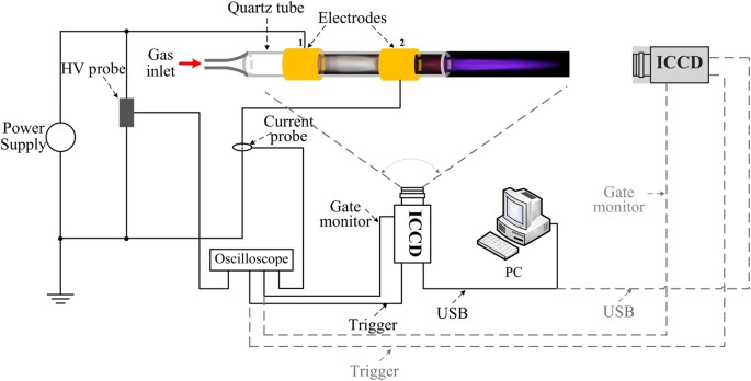
Experimental schematic.
The dynamic images of the plasma “bullet” were captured by two ICCDs with the same model (Andor iStar 334T) which were synchronously triggered. The current and voltage signals were taken by employing a current probe Pearson 2877 and high voltage probe P6015A and were recorded with a digital oscilloscope. The electrode structure is shown in Fig. 2 which is the same as the electrode system used in our previous work 9 . The wider HV electrode with width of 10 cm is mainly used to eliminate the influence of discharge in DBD zone. First of all, the effects of size and the cross section shape of the dielectric tube on the structure of the plasma “bullet” are discussed. Then, the “bullet” in He APPJ driven by an AC power with 23 kHz of frequency (see Fig. 3(a) ) was investigated because Penning effect is inevitable there. Further, a positive pulse voltage with 0.5 Hz of frequency (see Fig. 3(b) ) was employed to generate a single discharge per single shot, where Penning effect can be effectively avoided because the active products in discharge will disappear during 2s of a cycle. At the same time, different ratio of impurity N 2 was added into the pure helium gas (analytical purity, 5N) channel in two experiments for knowing evolution of the hollow structure. In the end of the paper, supplementary material provides another experiment as one more example evidence which was conducted in Ar/NH 3 APPJ (Supplementary Information).
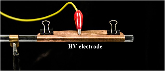
Experimental electrode configuration.
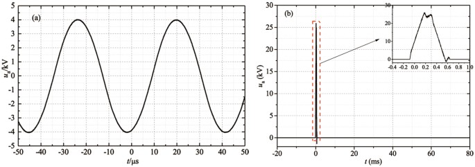
Applied voltage waveform: ( a ) AC with the frequency of 23 kHz. ( b ) Positive pulse with the frequency of 0.5 Hz.
Hollow structure of plasma “bullet” with different tube size and cross section shape
For the convenience of analysis, we proposed two terms “micro-hybrid interface zone” and “Penning ionization zone”. The former should stay between the carrier gas channel and ambient air due to the diffusion, entrainment and viscosity. The latter is defined as a zone with suitable mole fraction of He for Penning ionization. According to our previous work 17 , we compared the results of the experiment and the fluid simulation with and without APPJ. Mole fraction of helium in “Penning ionization zone” should follow a range from 98.7% to 99.8%. Therefore, micro-hybrid interface zone, which relies on the tube size and Reynold number (flow state), can’t be obviously changed in this paper. However, Penning ionization zone will be shrunk towards axis of gas channel because the mole fraction of helium is changed with different adding ratio of nitrogen into helium.
Different tube’s diameter
Two size (diameter d = 2 mm and d = 4 mm) quartz tube ( ε = 3.5–3.7) were employed. The ICCD images with 5 ns exposure time at 10 mm outside the tube nozzle are shown in Fig. 4(a,b) . The front view images are the hollow structure in both case of 2 mm (top panel in Fig. 4(a) ) and 4 mm (top panel in Fig. 4(b) ) tube’s inner diameter. The curves plotted in bottom panel in each image are normalized 1D lightness distribution along the solid yellow line on radial, respectively. From the curves, the hump shape presents in two cases, and it can further be found that the maximum of light intensity appears at r = 0.28 mm for d = 2 mm tube and r = 1.20 mm for d = 4 mm tube. Therefore, the hollow ring-shape structure of plasma “bullet” should have a minor dependence on the size of dielectric tube when the size is no less than a certain value (such as 0.5 mm of tube inner diameter) in this paper (more systematic experiments around the relation of tube diameter and the hollow structure not shown here). And another recalled things is that the conclusion gotten by Naidis in 2010 might be reassessed in which a solid shape plasma “bullet” existed in case of 0.25 cm radius of tube 11 .
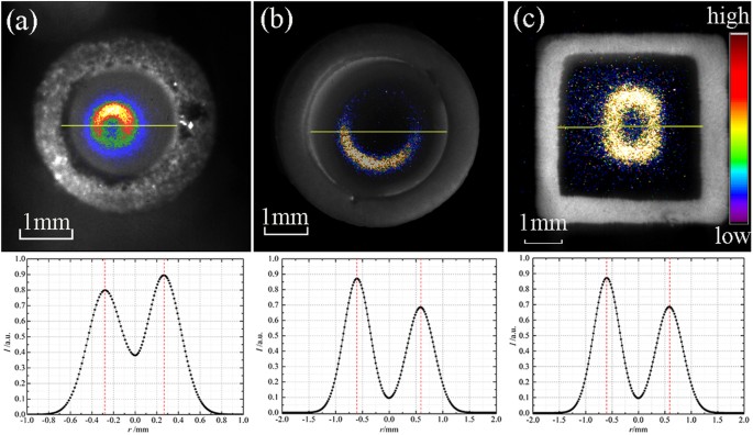
ICCD Images displayed in pseudo-color of different tube with normalized 1D lightness distribution: ( a ) glass tube of d = 2 mm, ( b ) glass tube of d = 4 mm, ( c ) ABS tube of L = 4 mm, exposure time: 5 ns.
Different tube’s cross section shape
Also, to compare with the case of circle cross section shape, a ABS (Acrylonitrile–Butadiene–Styrene copolymer) tube ( ε = 2.2–2.5) with square cross section of 4 mm length was used as a dielectric material to generate a helium plasma jet driven by a power the same as aforementioned. If an ICCD was focused at the position of 10 mm away from the tube nozzle, we can get an instantaneous image of plasma “bullet” in a hollow square shape, as shown top panel in Fig. 4(c) . Analogously, a normalized 1D lightness distribution along with the solid yellow line was drawn in bottom panel. A hump shape is, obviously, obtained and the lightness peak appears at r = 0.6 mm.
The hollow structure of plasma “bullet” always presents whatever ring-shape or square-shape, not the size (when the “micro-hydro interface zone” and “Penning ionization zone” can be identified) and materials of tube. It is consistent with the analysis from Breden 13 where dielectric with higher breakdown strength (just as a solid dielectric or air gas) exists around the helium gas channel and forms a guided gas channel. They can influence the propagation of the plasma “bullet” just like a guided streamer but not a common streamer.
Penning effect versus hollow structure
In this section, contribution and influence of the penning effect on the hollow structure of helium plasma “bullet” were obtained by controlling the power types and added ratio of N 2 in experiment. In order to clearly observe the structure of the plasma “bullet”, a quartz tube with inner/outer diameters of 5.5 mm/8 mm was used here. To synchronously capture the plasma “bullet” images from side view and front view, two ICCDs in the same model and with the same parameters sets were placed in orthometric directions as shown in Fig. 1 .
Plasma driven by AC with 23 kHz
In case of AC power source with 23 kHz frequency, called “continuous discharge” here, the applied voltage (Fig. 3(a) ) and the discharge current waveforms are given in Fig. 5 .
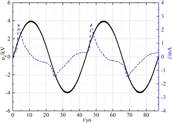
Current and applied AC voltage waveforms.
The images of plasma “bullet” with/without impurity N 2 were captured by ICCDs and composited by image treatment software Photoshop © , shown in Fig. 6 . In each image in pseudo-color, the side-view and the front-view photos of the “bullet” at the same moment and position are respectively shown on left and right sides of the yellow solid line. The ratio of added nitrogen gas covers from 0sccm to 25sccm with changing step of 5sccm. Figure 6 presents a hollow structure captured in case of pure helium and a little impurity N 2 added (such as N 2 flow rate of 5sccm). The front-view photo gradually transits from hollow into solid shape when the ratio of N 2 exceeds a certain value, such as 10sccm.
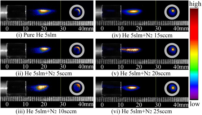
Side- and front-view in pseudo-color of plasma “bullet” driven by an AC power with 23 kHz of frequency, exposure time: 5 ns.
Plasma driven by positive pulse with 0.5 Hz
As well known, Penning reaction happens between the metastable atomic He, produced in previous discharge, and some N 2 whose ionization energy is slightly less than excited energy of the metastable atoms. It can provide more seed electrons for discharge. So it is difficult to avoid Penning effect in case of high frequency continuous discharge.
In order to eliminate this influence, a positive pulse with width of 400 μ s is written with an arbitrary waveform generator and is outputted after amplified by a high voltage amplifier, as shown in Fig. 3(b) . Only single discharge (namely one current pulse per voltage pulse) was generated during this positive pulse, whose current waveform is shown in Fig. 7(a,b) . Because of non-repeatability of single discharge, it is very difficult and time-consuming to get the ICCD image of plasma “bullet” with head just located at around 10 mm outside the nozzle. Therefore, the specific operates procedure described in Section Methods needs to be followed in oder to achieve this aim.
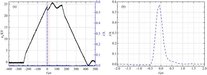
Current and applied pulsed voltage waveforms ( a ), and enlarged current waveform ( b ).
The axial and radial ICCD images in pseudo-color for plasma “bullet” with 2 ns exposure time at 10 mm outside the nozzle, captured during single discharge and with different N 2 addition, are shown in Fig. 8 . Both of the images respectively locate on the left and right side of the yellow vertical bar in each figure. It can be seen that all the radial images of plasma “bullet” generated by single discharge present a relatively homogeneous hollow structure at 10 mm outside the nozzle, whatever for pure He or with N 2 addition. Compared with high frequency continuous discharge described in last section, hollow structure in the single pulse discharge always exists, being not affected by N 2 ratio, as shown in Fig. 8 .
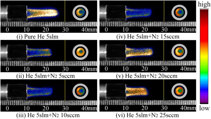
Side- and front-view in pseudo-color of plasma “bullet” driven by an pulse power with 0.5 Hz of frequency, exposure time: 2 ns.
On basis of the above experimental results, we give some discussions as follows. We will firstly discuss the gas flow status. Reynold number ( R e ), a typical parameter for expressing the status of fluid, can be calculated according to the definition of fluid in tube as follow. It is usually expressed as formula \({R}_{{\rm{e}}}=\frac{\rho {D}_{{\rm{H}}}u}{\mu }=\frac{Q{D}_{{\rm{H}}}}{\nu A}\) , where D H is the hydraulic diameter of the pipe (the inside diameter if the pipe is circular) (m), Q is the volumetric flow rate (m 3 s −1 ), A is the pipe’s cross-sectional area (m 2 ), u is the mean velocity of the gas (ms −1 ), μ is the dynamic viscosity of the gas (kg (m ⋅ s) −1 ) (for helium gas, μ = 1.9561 × 10 −5 kg (m ⋅ s) −1 ), ν is the kinematic viscosity ( \(\nu =\frac{\mu }{\rho }\) (m 2 s −1 ), ρ is the density of the fluid (kgm −3 ) (for helium gas, ρ = 0.16674 kgm −3 ). For helium gas flow inside glass tube, it is a laminar flow because the R e is nearly equal to 164 which is far less than the critical value (generally, laminar flow presents when R e < 2320 while the turbulent flow occurs when R e > 2600, and the transition flow appears when R e is between 2300 and 2600). The fluid at position a few centimeters downstream the nozzle can also be deemed as inside tube because the air ambient can act as a “tube”, which can be justified from the schlieren image in experiment 17 , 18 and from the velocity and species distributions in fluid simulation 17 . Therefore, it means that the helium gas flow is completely laminar flow in our experiment. Based on the description in fluid mechanics, the laminar model of flow status, the velocity distribution and the shear stress distribution inside circular tube can typically be shown in Fig. 9(a–c) , respectively. Under laminar flow, the gas flow just like a set of countless thin cylinders (Fig. 9(a) ). The higher the velocity is, the smaller diameter of the cylinder is. On the edge of gas channel, the flow rate is close to zero because of shear stress (Fig. 9(b,c) ). Therefore, in our experiment, (1) the analytic purity helium gas with laminar flow is injected into the ambient air, forming a helium channel surrounded by air. (2) A “micro-hybrid interface zone” is built at the interface between helium channel and air due to diffusion, entrainment and viscosity.
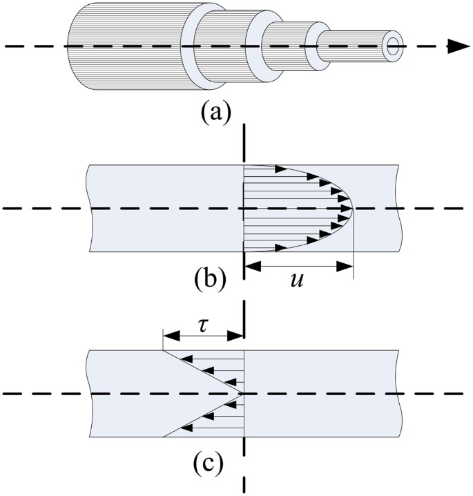
Schematic of laminar flow inside circular tube. ( a ) laminar model; ( b ) velocity distribution; ( c ) shear stress distribution.
When we apply continuous voltage with high frequency, such as AC power with 23 kHz of frequency, (1) A lot of metastable He atoms with ∼ 10 μ s lifetime generated in previous discharge will live inside the whole gas channel and have Penning reaction with the N 2 molecule following the main reactions such as, He m + N 2 → He + \({{\rm{N}}}_{2}^{+}\) + e, k = 7 × 10 −11 cm −3 s −1 ; He m + O 2 → + \({{\rm{O}}}_{2}^{+}\) + e, k = 2.5 × 10 −10 cm −3 s −1 19 . It can produce abundant seed electrons for generating subsequent discharge. This process will make the discharge happen in this zone firstly. (2) The reactions, such as excitation and re-excitation, are frequent in that zone, leading to an optical ring-shape. (3) By increasing N 2 in helium gas channel, the mole distribution of He atom and N 2 molecule was meanwhile changed. When the ratio of N 2 reaches a certain value, the quenching reactions from N 2 will surpass the Penning reactions, and then the Penning ionization zone aforementioned will collapse to axis of gas channel making the shape of the plasma transit from the hollow into the contracted solid shape.
Further, we extract the lightness data along the direction of 135 degrees on radial photos which lies on right panel in each sub-images. The data extracted were normalized and plotted as 1D curve shown in Fig. 10(a–f) . We can clearly see the hollow structure distribution in case of pure He 5slm and He 5slm + N 2 5sccm. The peak position of the 1D light curves, representing the most violent excitation and deexcitation reactions, respectively locate at r ≈ 1.05 mm, 0.98 mm, 0.93 mm for pure He 5slm (ratio of N 2 is zero), He 5slm + N 2 5sccm (ratio of N 2 is nearly 0.1 %) and He 5slm + N 2 10sccm(ratio of N 2 is nearly 0.2 %). It means that Penning effect play a dominate role when the ratio of impurity N 2 is no more than about 0.2 %. At this moment, the ratio of impurity N 2 in the two zones aforementioned must be higher than mix ratio of N 2 into pure helium. It agrees well with the numerical simulation results 17 . The quenching effect from N 2 will over the Penning effect and play a key role when the ratio is larger than about 0.2 %. The quantitative analysis will be further done by mix gas fluid model with or without discharge in future.
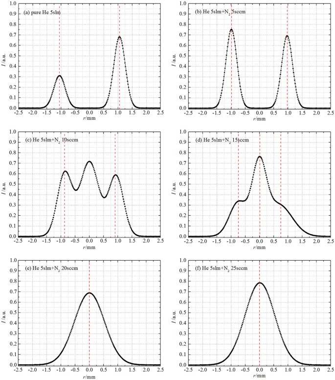
Applied voltage: AC, normalized 1D lightness distribution of front-view ICCD images along radial with different N 2 ratio: ( a ) N 2 0sccm; ( b ) N 2 5sccm; ( c ) N 2 10sccm; ( d ) N 2 15sccm; ( e ) N 2 20sccm; ( f ) N 2 25sccm.
So in case of continuous discharge, we can find that the radial optical shape of plasma “bullet” at 10 mm outside nozzle has a dynamic evolution when the ratio of N 2 and He is changed. It expresses that Penning effect plays a key role for maintaining the hollow structure of plasma “bullet” and its transition. However, its contribution to formation of the hollow structure can not be confirmed only depending on the experiment here.
As shown in single pules discharge, the radial image of plasma “bullet” is always hollow structure, not influenced by ratio of impurity N 2 in present work. The normalized 1D lightness distributions along the direction of 135 degrees on radial ICCD images, in Fig. 11(a–f) , also support this point. Two separative peaks have been obtained for each case. The statistic peaks position in all cases is around r ≈ 1.4 mm which is larger than that of continuous discharge. In this experiment, metastable He atoms from previous discharge need not to be considered because only single pulse was applied on electrode per discharge. If must be considered, the metastable He atoms should just be generated during the whole pulse. It can be estimated that metastable He atoms, even if produced before discharge and during current pulse, can only move about 3–4 mm during this period driven by gas flow but can not arrive at 10 mm outside the nozzle. That is to say that the “Penning ionization zone” does not present, so that Penning reactions relevant to metastable He atoms can not happen in the interest area. Therefore, it is reasonable to ignore the direct contribution of Penning effect to generating the hollow structure of plasma “bullet”. It means that Penning ionization has no effect on forming the hollow structure of plasma “bullet”.
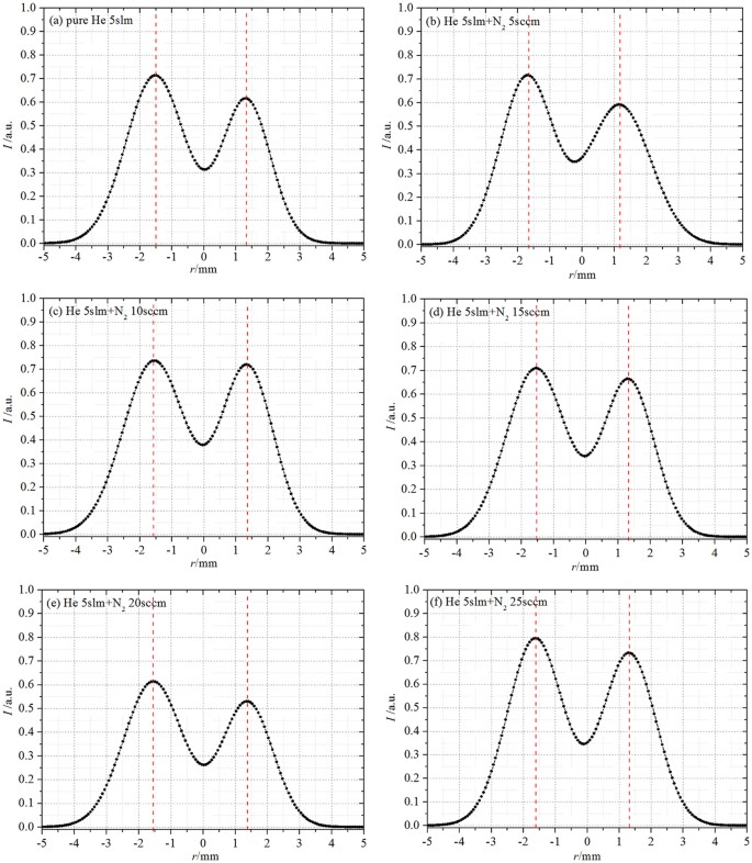
Applied voltage: Pulse, normalized 1D lightness distribution of front-view ICCD images along radial with different N 2 ratio: ( a ) N 2 0sccm; ( b ) N 2 5sccm; ( c ) N 2 10sccm; ( d ) N 2 15sccm; ( e ) N 2 20sccm; ( f ) N 2 25sccm.
Naidis 16 , in numerical simulation research, thought that direct collision ionization of electrons at He/Air interface is the main reason for formation of annular “bullet” in development process of discharge plasma. If it’s true, the direct ionization zone should move to axis of plasma jet with increasing N 2 addition ratio, making radial image of discharge gradually transform into solid. But the results in Figs 8 and 11 are clearly opposite with this explanation.
Except for the factors abovementioned, high breakdown voltage dielectric “tube”, guided laminar gas flow and photo-ionization should be reconsidered for forming the plasma “bullet” with hollow structure. As analyzed, “micro-hybrid interface zone” always exists whatever in high frequency continuous discharge or in single pulse discharge, providing a guide channel for development of discharge. In case of single pulse discharge, discharge ignited from the edge of HV electrode propagates along the surface of inner wall of the tube (see above analysis about laminar gas flow) and goes into the carrier gas flow “tube” continuously. The photo-ionization on head of plasma “bullet” provides advantage for further propagation of discharge 2 in micro-hybrid interface zone. It should be the most convictive reason for the formation of APPJ hollow structure.
In conclusion, we discussed the formation and evolution of the plasma “bullet” with hollow structure by designing several special experiments. The role of penning effect was also analyzed. Several key conclusions obtained in this paper are listed here: (1) Penning effect plays a minor role in generating hollow structure of plasma “bullet”, but has important contribution to maintaining and evolving the hollow structure when the plasma driven by a continuous discharge. (2) The formation of hollow structure mainly results from guided laminar gas flow and photo-ionization at head of plasma “bullet”. (3) Advanced supposition can be made that the hollow structure of plasma “bullet” should be a characteristic of glow-like APPJ in open ambient. Although we can not provide a strong analysis to support our assumption, we just give one more experiment in Ar/NH 3 APPJ as an example evidence (Supplementary Information).
Gas mixture and control
In this paper, two kinds of gases with a large flow rate difference, one is high flow rate (such as helium, argon) and another is low flow rate (such as N 2 , NH 3 ), need to be mixed before inlet the quartz tube. In order to get homogeneous mixture, we designed single direction hybrid resonator with two channels in and one channel out as well as filled with micro-porous material. Before starting experiment every time, we turn on the gas valves and let gases run over 5 min. After that, power can be turned on to generate discharge and next measurement starts. For low flow rate (like few sccm) and corrosive gas, the special controller with small scale and anti-corrosion material valves is necessary.
ICCD trigger set and images capture
For AC with 23 kHz discharge, the ICCD images at interest position are easily taken by normal method which has been widely used by researchers. For single discharge, it was a bit complex to capture the ICCDs images at specific position, such as at 10 mm outside nozzle. We employ a relatively unadvanced method here. Two ICCDs are synchronously triggered by voltage and current signals, via setting AB sequence triggering on an LeCroy WaveSurfer 104MXs-B © oscilloscope with 10 GS/s of Sampling rate and 1 GHz of bandwidth. Specifically, condition for “A” event is satisfied → oscilloscope stand-by → condition for “B” event is satisfied → oscilloscope outputs trigger TTL signal → ICCDs response and wait → ICCDs delay time set on software is satisfied → ICCDs act and response signals are monitored by monitor gate and cable. For each case in Fig. 8 , many shots (up to 1200) are usual. Two ICCDs should focus on the position 10 mm downstream of nozzle. Among these shots, we should get the right ICCD images at the interest position at least 3 times and select one of them.
Teschke, M., Kedzierski, J., Finantu-Dinu, E. G., Korzec, D. & Engemann, J. High-speed photographs of a dielectric barrier atmospheric pressure plasma jet. IEEE Transactions on Plasma Science 33 , 310–311 (2005).
Article ADS Google Scholar
Lu, X. P. & Laroussi, M. Dynamics of an atmospheric pressure plasma plume generated by submicrosecond voltage pulses. Journal of Applied Physics 100 , 391 (2006).
Article Google Scholar
Mericambourdet, N., Laroussi, M., Begum, A. & Karakas, E. Experimental investigations of plasma bullets. Journal of Physics D Applied Physics 42 , 055207 (2009).
Karakas, E., Begum, A., Koklu, M. & Jarrige, J. Experimental investigations of ring-shaped plasma bullets emitted by a pulsed plasma jet. In Pulsed Power Conference, 2009. PPC 09. IEEE , 1129–1132 (2009).
Urabe, K., Morita, T., Tachibana, K. & Ganguly, B. N. Investigation of discharge mechanisms in helium plasma jet at atmospheric pressure by laser spectroscopic measurements. Journal of Physics D Applied Physics 43 , 095201 (2010).
Sakiyama, Y., Graves, D. B., Jarrige, J. & Laroussi, M. Finite element analysis of ring-shaped emission profile in plasma bullet. Applied Physics Letters 96 , 310 (2010).
Leiweke, R. J., Sands, B. L. & Ganguly, B. N. Effect of gas mixture on plasma jet discharge morphology. IEEE Transactions on Plasma Science 39 , 2304–2305 (2011).
Article ADS CAS Google Scholar
Wu, S., Huang, Q., Wang, Z. & Lu, X. The effect of nitrogen diffusion from surrounding air on plasma bullet behavior. IEEE Transactions on Plasma Science 39 , 2286–2287 (2011).
Chang, Z., Jiang, N., Zhang, G. & Cao, Z. Influence of penning effect on the plasma features in a non-equilibrium atmospheric pressure plasma jet. Journal of Applied Physics 115 , 1223 (2014).
Xian, Y. B. et al . On the mechanism of ring-shape structure of plasma bullet. Plasma Processes and Polymers 11 , 1169–1174 (2015).
Naidis, G. V. Modelling of streamer propagation in atmospheric-pressure helium plasma jets. Journal of Physics D Applied Physics 43 , 402001 (2010).
Naidis, G. V. Modelling of plasma bullet propagation along a helium jet in ambient air. Journal of Physics D Applied Physics 44 (5), 215203–215207 (2011).
Breden, D., Miki, K. & Raja, L. L. Computational study of cold atmospheric nanosecond pulsed helium plasma jet in air. Applied Physics Letters 99 , 113902–1 (2011).
Breden, D., Miki, K. & Raja, L. L. Self-consistent two-dimensional modeling of cold atmospheric-pressure plasma jets/bullets. Plasma Sources Science and Technology 21 , 034011 (2012).
Boeuf, J. P., Yang, L. L. & Pitchford, L. C. Dynamics of a guided streamer (‘plasma bullet’) in a helium jet in air at atmospheric pressure. Journal of Physics D Applied Physics 46 , 015201 (2013).
Naidis, G. V. On the ring-shaped structure of helium plasma jets. IEEE Transactions on Plasma Science 43 , 733–736 (2015).
Shao, X. Comparative study on characteristics and mechanism of helium and argon atmospheric pressure plasma jets under kHz AC high voltage . Ph.D. thesis, Xi’an Jiaotong University (2012).
Foletto, M., Puech, V., Fontane, J., Joly, L. & Pitchford, L. C. Evidence of the influence of plasma jets on a helium flow into open air. IEEE Transactions on Plasma Science 42 , 2436–2437 (2014).
Sommerer, T. J. & Kushner, M. J. Numerical investigation of the kinetics and chemistry of rf glow discharge plasmas sustained in He, N 2 , O 2 , He/N 2 /O 2 , He/CF 4 /O 2 , and SiH 4 /NH 3 using a monte carlo-fluid hybrid model. Journal of Applied Physics 71 , 1654–1673 (1992).
Download references
Acknowledgements
This work was partially funded by the National Natural Science Foundation (Grant Nos 51777165, 11775175, 51307133), China Postdoctoral Science Foundation (Grant Nos 2017T100749, 2016M590946), the Fundamental Research Funds for the Central Universities (Grant No. xjj2016003).
Author information
Authors and affiliations.
State Key Laboratory of Electrical Insulation and Power Equipment, The School of Electrical Engineering, Xi’an Jiaotong University, Xi’an, 710049, P. R. China
Zhengshi Chang, Ni Zhao, Guoqiang Li & Guanjun Zhang
You can also search for this author in PubMed Google Scholar
Contributions
Z.C. led the project and conceived as well as conducted all the experiments. N.Z. and G.L. conducted the experiments and analyzed the data. Z.C. and N.Z. wrote the whole manuscript. Z.C. and G.Z. analyzed and discussed the data and results. All authors reviewed the manuscript.

Corresponding authors
Correspondence to Zhengshi Chang or Guanjun Zhang .
Ethics declarations
Competing interests.
The authors declare no competing interests.
Additional information
Publisher's note: Springer Nature remains neutral with regard to jurisdictional claims in published maps and institutional affiliations.
Electronic supplementary material
Supplementary information, rights and permissions.
Open Access This article is licensed under a Creative Commons Attribution 4.0 International License, which permits use, sharing, adaptation, distribution and reproduction in any medium or format, as long as you give appropriate credit to the original author(s) and the source, provide a link to the Creative Commons license, and indicate if changes were made. The images or other third party material in this article are included in the article’s Creative Commons license, unless indicated otherwise in a credit line to the material. If material is not included in the article’s Creative Commons license and your intended use is not permitted by statutory regulation or exceeds the permitted use, you will need to obtain permission directly from the copyright holder. To view a copy of this license, visit http://creativecommons.org/licenses/by/4.0/ .
Reprints and permissions
About this article
Cite this article.
Chang, Z., Zhao, N., Li, G. et al. Plasma “bullet” with hollow structure: formation and evolution. Sci Rep 8 , 7599 (2018). https://doi.org/10.1038/s41598-018-25962-z
Download citation
Received : 18 December 2017
Accepted : 02 May 2018
Published : 15 May 2018
DOI : https://doi.org/10.1038/s41598-018-25962-z
Share this article
Anyone you share the following link with will be able to read this content:
Sorry, a shareable link is not currently available for this article.
Provided by the Springer Nature SharedIt content-sharing initiative
This article is cited by
The ring-shaped spatial distribution of the argon excimer, \(\hbox {ar}_2^{*}\) , in the effluent of the kinpen-sci.
- Andy S. C. Nave
- Philipp Mattern
- Jean-Pierre H. van Helden
Scientific Reports (2024)
Role of charge accumulation in guided streamer evolution in helium DBD plasma jets
- Mikhail Pinchuk
- Anton Nikiforov
- Olga Stepanova
Scientific Reports (2021)
Quick links
- Explore articles by subject
- Guide to authors
- Editorial policies
Sign up for the Nature Briefing newsletter — what matters in science, free to your inbox daily.

We apologize for the inconvenience...
To ensure we keep this website safe, please can you confirm you are a human by ticking the box below.
If you are unable to complete the above request please contact us using the below link, providing a screenshot of your experience.
https://ioppublishing.org/contacts/

Experimental studies on the plasma bullet propagation and its inhibition
Electronic mail: [email protected] .
Electronic mail: [email protected] .
- Article contents
- Figures & tables
- Supplementary Data
- Peer Review
- Reprints and Permissions
- Cite Icon Cite
- Search Site
Erdinc Karakas , Mounir Laroussi; Experimental studies on the plasma bullet propagation and its inhibition. J. Appl. Phys. 15 September 2010; 108 (6): 063305. https://doi.org/10.1063/1.3483935
Download citation file:
- Ris (Zotero)
- Reference Manager
Plasma bullets generated by atmospheric pressure low temperature plasma jets have recently been an active research topic due to their unique properties and their enhanced plasma chemistry. In this paper, experimental insights into the plasma bullet lifetime and its velocity are reported. Data obtained from intensified charge-coupled device camera and time-resolved optical emission spectroscopy (OES) elucidated the existence of a weakly ionized channel between the plasma bullet and its source (such as the plasma pencil). Factors responsible for the inhibition of the propagation of the bullet, such as low helium mole fraction, the magnitude of the applied voltage, and the secondary discharge ignition time, are also revealed. A new technique is discussed to accurately measure the plasma bullet velocity, using time-resolved OES. This new technique shows that during its lifetime the plasma bullet goes through launching, propagation, and ending phases. In addition, it is noted that the plasma bullet exhibits an unstable behavior at the early beginning and late ending of the propagation.
Citing articles via
Submit your article.

Sign up for alerts

Related Content
- Online ISSN 1089-7550
- Print ISSN 0021-8979
- For Researchers
- For Librarians
- For Advertisers
- Our Publishing Partners
- Physics Today
- Conference Proceedings
- Special Topics
pubs.aip.org
- Privacy Policy
- Terms of Use
Connect with AIP Publishing
This feature is available to subscribers only.
Sign In or Create an Account

IMAGES
VIDEO
COMMENTS
Here we present experimental insights into the physical and chemical characteristics of bullets. We show that their time of initiation, their velocity and the distance they travel are directly dependent on the value of the applied voltage.
Sakiyama et al. 6 thought that air diffusion against helium convection creates the unique ring-shape emission profile in plasma “bullets” by employing experimental observation and finite...
Here we present experimental insights into the physical and chemical characteristics of bullets. We show that their time of initiation, their velocity and the distance they travel are directly dependent on the value of the applied voltage.
Here we present experimental insights into the physical and chemical characteristics of bullets. We show that their time of initiation, their velocity and the distance they travel are directly dependent on the value of the applied voltage.
There are various optical and electrical methods to investigate the parameters of plasma jets such as intensi・‘d CCD (ICCD) imaging, optical emission spectroscopy (OES), avalanche photodiode (APD), Schlirien photography etc.
Numerous experimental and numerical investigations have been performed on plasma jets and plasma bullets [ 7 ]. In the large majority of these studies, a noble gas (He, Ar, Ne or Kr) or a noble gas mixture is used as feed gas, sometimes with small admixtures of molecular species (N 2, O 2 or H 2 O).
Plasma bullets generated by atmospheric pressure low temperature plasma jets have recently been an active research topic due to their unique properties and their enhanced plasma chemistry. In this paper, experimental insights into the plasma bullet lifetime and its velocity are reported.
Here we present experimental insights into the physical and chemical characteristics of bullets. We show that their time of initiation, their velocity and the distance they travel are directly dependent on the value of the applied voltage.
The generation of extremely stable light bullets in a preformed plasma near critical density has been observed experimentally during the interaction of intense picosecond laser beam with a metallic target in air.
Data obtained from intensified charge-coupled device camera and time-resolved optical emission spectroscopy (OES) elucidated the existence of a weakly ionized channel between the plasma...