BreadBoardCircuits.com
Applied Theory on a Breadboard

Ohm’s Law – Hands On
Hands on ohm’s law project, project overview.
As with any lab project on BreadBoardCircuits.com , building the circuits are recommended, but not necessary. If you wish to just read along, you will still get a great deal of useful information out of the article.
With this beginner’s project, you will learn Ohm’s Law basics and beyond – in theory and on the breadboard. You’ll calculate the current through a single resistor and confirm that calculation with a amp-meter measurement. You will then create a parallel resistor arrangement, calculate the equivalent resistance, and the current through each resistor. You’ll then move on to a series arrangement and learn about the voltage divider and how to calculate the voltage across each resistor. After confirming your calculations on the breadboard, you will have an understanding about how current flows and is distributed, as well as how voltage appears and is divided. Finally, you will learn how to calculate power and how changes in voltage and current affect power output. To learn exactly what voltage and current are, please see this article first.
Before building a breadboard, please review our safety procedures and recommendations page.
Supplies Needed
- Minimum breadboarding equipment (see here)
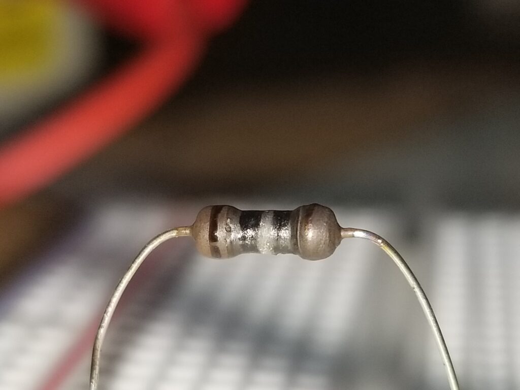
- (3) 1k Ohm 1/4 watt resistors
- (1) 470 Ohm 1/4 watt resistor
Ohm’s Law
According to “Ohm’s law”, the current through a load, such as a resistor is proportional to the voltage across that load. This yields the Ohm’s law triangle as shown in the image below.
Where V = voltage, I = current, and R = resistance.

The Ohm’s law triangle readily shows the mathematical relationship between the the three variables. Thus, if you want to find voltage, you multiply the I and the R at the bottom. If you want to find current, you divide V by R. To find resistance, you divide V by I. For DC circuits, finding V, I, or R is as simple as plugging in the values. For AC RMS voltage , when using resistive loads, Ohm’s law can be equally applied as described above.
Experiment #1 – Current through a Single Resistor
We’ll demonstrate Ohm’s law in simple form by applying a voltage across a single resistor. A voltage of 10 volts DC will be connected across a 1k ohm resistor. The calculated current, based on the Ohm’s law triangle is (10 volts)/(1000 ohms) = 0.01 amps or 10 milliamps (mA). This is the value that we would expect to measure with an amp meter. Traditionally, an amp meter is connected in parallel with the circuit. We will use a Fluke multimeter to do this. Below is shown both the schematic for this experiment as well as the breadboard and associated measurements.
Note that if we reduce the voltage to 5 volts, the current proportionally decreases to 5 mA, which corresponds to the Ohm’s law equation per the triangle. The measurements are shown below.
Picture here

Experiment #2 – Resistors in Parallel
Parallel resistors increase the total current flow through the circuit. Thus, the equivalent value of 2 parallel resistors is always less than the value of either one.
Equivalent Resistance
The equivalent resistance of parallel resistors is calculated by 1/Rp = 1/R1 + 1/R2 + 1/R3 ….., where Rp is “R parallel” or the parallel equivalent resistance. If you only have 2 parallel resistors, you can use the shortcut equation Rp = (R1 x R2)/(R1 + R2).
Let’s connect (2) 1k resistors in parallel. Based on the first equation above, we have 1/Rp = 1/1000 + 1/1000. Thus Rp = 1000/2 or 500 ohms. Using the shortcut equation, we have (1000 x 1000)/(1000+1000) = 1000000/2000= 500 Ohms.
Below is a breadboard with 2 parallel 1k ohm resistors. Note that the equivalent resistance that the Fluke multimeter reads is approximately 500 ohms.

Current through Parallel Resistors
Two resistors in parallel, such as in the above experiment, doubles the circuit current. The proportionality of Ohm’s law requires it. Let’s re-use the last experiment. We have two 1k ohm resistors in parallel. That is 500 ohms. If we apply 10 volts DC across that circuit, we should have (10 volts) / (500 ohms) = 20 mA . This is confirmed by measurement (below). That 20mA is being divided equally among the two resistors. How do we know that? It is simple. Each resistor has 10 volts across it. We know the value of each resistor. Thus 10 volts across each 1k resistor is 10mA per Ohm’s law. The current through each resistor adds up to 20 mA. The current division can be calculate by the formula: IR1 = Itotal x (R2/(R1+R2)) and IR2 = Itotal x (R1/(R1+R2)) . So calculating for IR1, we have 10mA x (1k/(1k + 1k)) = 10mA x (1k/2k) = 10mA x 1/2 = 5mA . Calculating for IR2, we have we have 10mA x (1k/(1k + 1k)) = 10mA x (1k/2k) = 10mA x 1/2 = 5mA .
This is verified by testing the current trough each resistor using the Fluke multimeter as shown below:

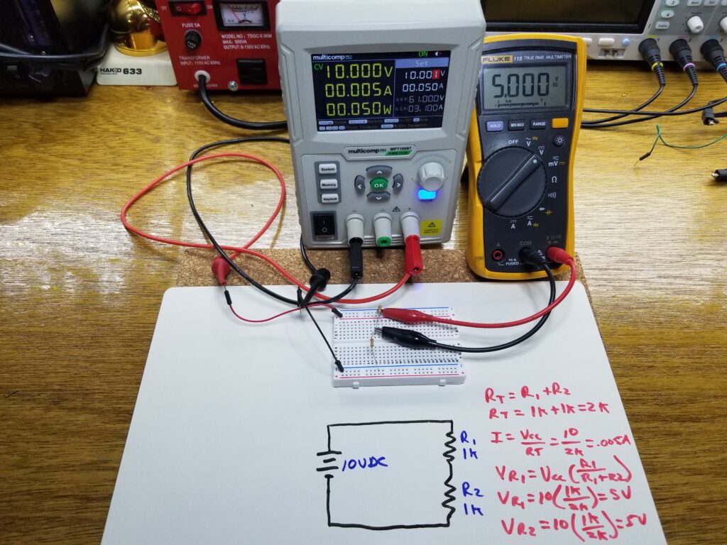
Experiment #3 – Resistors in Series and Equivalent Resistance
The resistance of series resistors is much easier to calculate. It is simply the sum of the resistances. Thus two 1k ohm resistors in series has a total resistance of 2k ohms. This is shown in the images below.
Current through Series Resistors
The current through series resistors is the same through each resistor and equals the total circuit current. Thus a circuit with two 1k ohm resistors in series has a total resistance of 2k ohms and a current of 5 mA, which is the same all through the circuit.

Schematic picture with breadboard
Experiment #4 – Voltages Across Series Resistors – The Voltage Divider
An important and often used configuration in electronics is the voltage divider. It is the basis for many types of circuits. It is based on series the resistance as described previously. In fact, to demonstrate it, we will use the same configuration as in the previous experiment. You have two 1k ohm resistors in series and a 10 volt source across the circuit. Just like current in parallel circuits, the inverse is true with voltage in series circuits. The voltage is divided between the series resistors. The sum of all the divided voltages adds back up to the source voltage. The formula for this is as follows: Vr1 = Vsource x (R1/(R1+R2) and Vr2 = Vsource x (R2/(R1+R2) . Let’s first try this with the two 1k resistors. The formula for the voltage across each resistor above yields 5 volts each. This is confirmed with the breadboard measurements.
Now lets use 1k ohms for R1 and 470 ohms for R2. In this case the voltage across each resistor will not be the same. To calculate the voltage across R2 you have Vr2 = Vsource x (R2/(R1+R2) = 10v x (470/(1k +470) = 10v x (470/1470) = 3.2v. This is confirmed on the breadboard measurements below.

So you can see how useful voltage dividers can be. If you wanted to create a 3.2 volt source for any reason, out of a 10 volt source, you could do it in the above manner.
Experiment #5 – Power
Electrical power is defined as the rate (per time) that electrical energy is transferred by a circuit. Electrical power is measured in watts, which equates to one joule of energy per second. Current flowing through a resistor will generate heat. The heat that the resistor dissipates is measured in watts and can be calculated by the following equations using current, resistance, and voltage: P= VxI or P = I²xR or P=V²/R . To illustrate the heat generated by a resistor, we will take a 470 ohm, 1/4 watt resistor and connect enough voltage across it to generate 1/4 watt (the same as what the resistor is rated for). That voltage is 10.8 volts. Let’s calculate the power. P=V²/R, thus P=(10.8 x 10.8)/470 = 0.248 watts. Since the resistor is a 1/4 watt resistor, the resistor will be dissipating its maximum rated power and will be too hot to touch. In fact it will burn your finger if you try.

Power Increase by Voltage
What happens if you double the voltage across a resistor. Will the power (heat output) double? No. It increases by a factor of four. Let’s drop the voltage across the resistor from the previous experiment so that we have 1/8th of a watt being generated by it. That would be 7.65 volts. Let’s verify: P=V²/R, so (7.65×7.65)/470 = 0.125 watts (1/8th of a watt).
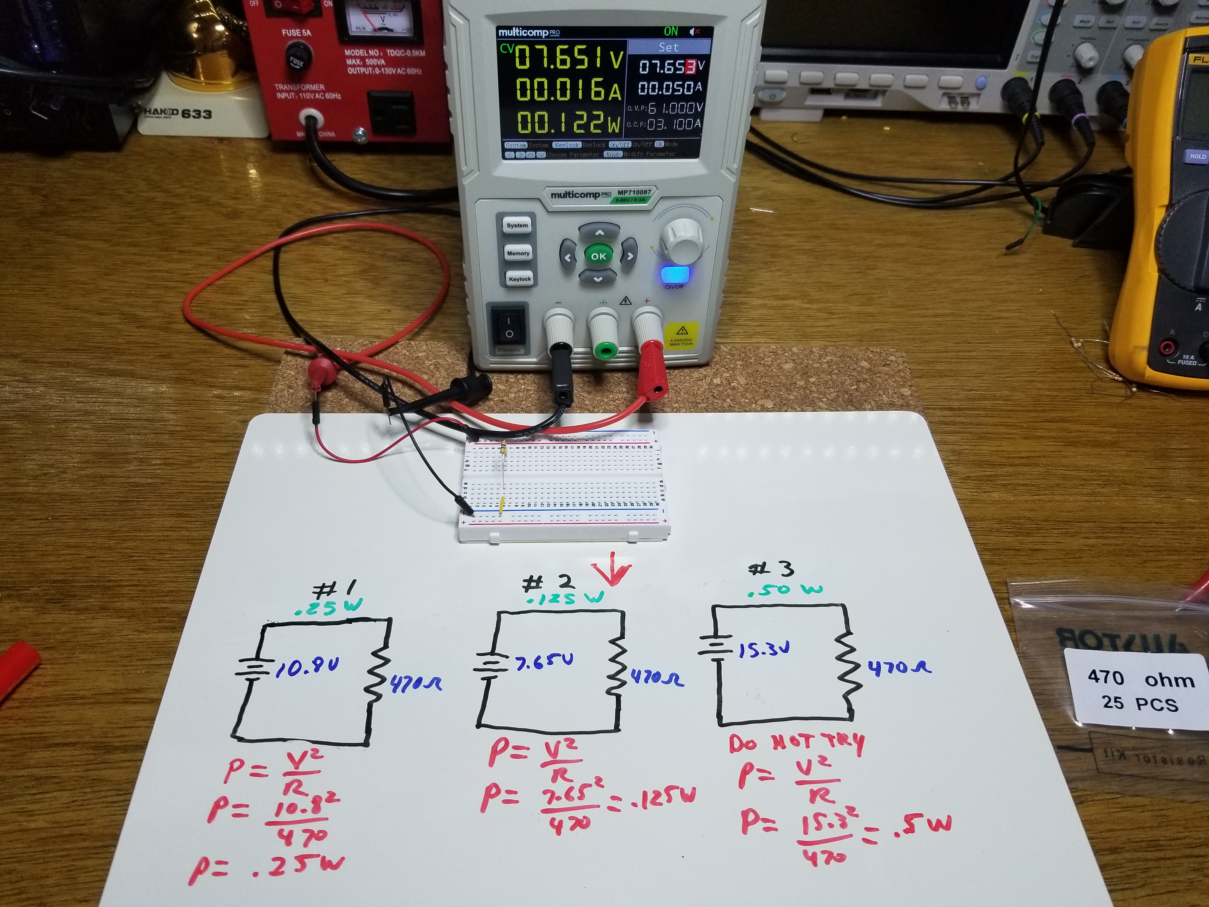
The following is not part of the experiment, and is just for illustration. If you were to double that voltage ( which you don’t want to do ), you would not have 1/4 watt of power, you would have four times that or 1/2 of a watt. That can be calculated by 7.65 x 2 = 15.3 volts. Since P=V²/R, you have (15.3×15.3)/470 = 0.498 watts. You don’t want to try this as the resistor will be hot enough to severely burn your finger. However, below is an image of the current flow, calculated power, and what would happen to the resistor.
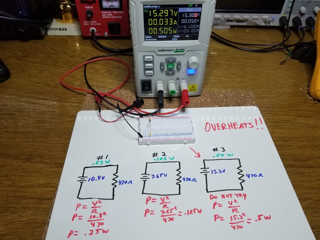
If you were to subject the resistor to this kind of wattage for long, it would just burn up, as illustrated in the two pictures below.
Current, voltage, Ohm’s law, Parallel and series resistances, current division, voltage dividers, and resistive power are all fundamental electrical concepts. They should be considered essential basic underpinnings for anyone interested in troubleshooting electronics or building circuits as a hobby. Understanding them will pay significant dividends going forward, where incomprehension of them will impede your electronics related endeavors.
For a better experience building breadboarded circuits, please see our page detailing the minimum recommended lab equipment for your electronics bench. Also, don’t forget to review the recommended safety procedures to follow when building and testing breadboarded circuits.
Finally, for other interesting breadboarded circuits please visit the home page here or our YouTube channel here. SM
We are a participant in the Amazon Services LLC Associates Program, an affiliate advertising program designed to provide a means for us to earn fees by linking to Amazon.com and affiliated sites.
- Network Sites:
- Technical Articles
- Market Insights

- Or sign in with
- iHeartRadio
- Intro Lab - Ohm’s Law
Join our Engineering Community! Sign-in with:
- DIY Electronics Projects
Basic Projects and Test Equipment
- Intro Lab - How to Use a Voltmeter to Measure Voltage
- Intro Lab - How to Use an Ohmmeter to Measure Resistance
- Intro Lab - How to Use an Ammeter to Measure Current
- Intro Lab - Resistor Power Dissipation
- Intro Lab - A Simple Lighting Circuit
- Intro Lab - Nonlinear Resistance
- Intro Lab - Circuit With a Switch
- Intro Lab - Build an Electromagnet
- Intro Lab - Electromagnetic Induction
Project Overview
This project employs all of the skills explained earlier in this textbook for using an ohmmeter , voltmeter , and ammeter . You will build a simple circuit, as illustrated in Figure 1, to experimentally verify Ohm's law which defines the mathematical relationship between resistance , voltage, and current.

Figure 1. Test circuit for evaluating Ohm's law.
Parts and materials.
- 6 V battery
- Assortment of resistors between 1 kΩ and 100 kΩ in value
For this experiment, I’m purposely restricting the resistance values between 1 kΩ and 100 kΩ for the sake of obtaining accurate voltage and current readings with your meter.
With very low resistance values, the internal resistance of the ammeter has a significant impact on measurement accuracy. Very high resistance values can cause problems for voltage measurement since the internal resistance of the voltmeter substantially changes circuit resistance when it is connected in parallel with a high-value resistor. At the recommended resistance values, there will still be a small amount of measurement error due to the impact of the meter, but not enough to cause serious disagreement with calculated values.
Learning Objectives
- Application of Ohm’s law
- Voltmeter use
- Ammeter use
- Ohmmeter use
Instructions
Step 1: Select a resistor from the assortment, and measure its resistance, R , with your multimeter set to the appropriate resistance range. Be sure not to hold the resistor terminals when measuring resistance, or else your hand-to-hand body resistance will influence the measurement! Record this resistance value for future use.
Step 2: Next, build the one-battery, one-resistor circuit, shown in the schematic diagram of Figure 2.

Figure 2. Test circuit schematic diagram for evaluating Ohm's law.
If you have two multimeters, you can construct exactly as shown in Figures 1 and 2 and measure both voltage and current simultaneously. However, in the following descriptions, we will assume you have only one multimeter and will perform the measurements in steps.
A terminal strip implementation of this circuit is demonstrated in Figure 1, but you can also use a breadboard or any other type of circuit construction method.
Step 3: Set your multimeter to the appropriate voltage range and measure the voltage, V , across the resistor as it is being powered by the battery. Record this voltage value.
Step 4: Set your multimeter to the highest current range available. Break the circuit and connect the ammeter within that break, so it becomes a part of the circuit, in series, with the battery and resistor.
Step 5: Select the best current range; whichever one gives the strongest meter indication without over-ranging the meter. If your multimeter is autoranging, of course, you need not bother with setting ranges. Record this current value along with the resistance and voltage values previously recorded.
Step 6: Taking the measured figures for voltage and resistance, use Ohm’s law equation to calculate circuit current.
$$I = \frac{V}{R}$$
- I = current in amps (A)
- V = voltage in volts (V)
- R = resistance in ohms (Ω)
Compare this calculated figure for the current with the measured figure for the circuit current. They should be identical (or very nearly so).
Step 7: Taking the measured figures for voltage and current, use Ohm’s law equation to calculate circuit resistance. Compare this calculated figure with the measured figure for circuit resistance.
$$R = \frac{V}{I}$$
Step 8: Finally, taking the measured figures for resistance and current, use Ohm’s law equation to calculate circuit voltage. Again, compare this calculated figure with the measured figure for circuit voltage.
$$V = I \cdot R$$
There should be close agreement between all measured and all calculated figures. Any differences in respective quantities of voltage, current, or resistance are most likely due to meter inaccuracies. These differences should be rather small, no more than several percent. Some meters, of course, are more accurate than others!
Step 9: Select different resistors are repeat steps 1 through 8. Re-take all resistance, voltage, and current measurements. Then, re-calculate these figures and check for agreement with the experimental data (measured quantities).
Also, note the simple mathematical relationship between changes in resistor value and changes in circuit current. Voltage should remain approximately the same for any resistor size inserted into the circuit because it is the nature of a battery to maintain voltage at a constant level.
Related Content
Learn more about the fundamentals behind this project in the resources below.
- Ohm's Law
Calculator:
- Ohm’s Law Calculator
- Resistor Color Code Calculator
Worksheets:
- Ohm's Law Worksheet
- Simple Circuits Worksheet
- Elementary Circuits Worksheet
- Basic Voltmeter Use Worksheet
- Basic Ohmmeter Use Worksheet
- Basic Ammeter Use Worksheet
- Textbook Index
Lessons in Electric Circuits
Volumes ».
- Direct Current (DC)
- Alternating Current (AC)
- Semiconductors
- Digital Circuits
- EE Reference
Chapters »
- 1 Introduction to Electronics Projects
Pages »
- 3 DC Circuit Projects
- 4 AC Circuit Projects
- 5 Discrete Semiconductor Circuit Projects
- 6 Analog IC Projects
- 7 Digital IC Projects
- 8 555 Timer Circuit Projects
- 9 Contributor List
- Advanced Textbooks Practical Guide to Radio-Frequency Analysis and Design
- Designing Analog Chips
- Ohm’s Law Calculator
- Silicon Labs Bluetooth Solutions
- Ohm’s Law
- Ohm’s Law, Kirchhoff’s Laws, and Power Equations
- Innovative Bluetooth Technology with Silicon Labs
- The Three Laws of Thermodynamics
You May Also Like

Innovate, Anticipate and Automate with Future Electronics
In Partnership with Future Electronics

onsemi’s Offline SMPS System Solution Guide
by Future Electronics

Simulating the Short-Circuit Power Dissipation of a CMOS Inverter
by Robert Keim

At Silicon Labs, Wireless IoT is Only The First Step in Rethinking Product Design
by Daniel Bogdanoff

Driving Industrial E-Mobility With Silicon Carbide Semiconductors
by Wolfspeed

Welcome Back
Don't have an AAC account? Create one now .
Forgot your password? Click here .
Something went wrong and we cannot process your request
There are a number of reasons why this might happen
The site might be down
You might have got caught by our bot protection logic
You might have tried to access a private document
To fix this you might try going back to the home page and trying again
If you still get this there, you may have either got caught by our bot protection, or the site may be down. Either way, go make a cup of warm brew, come back and try again, and it'll probably be resolved.
You might also check our twitter page
If you believe you have got this message in error, please report this citing this code
0.76c31302.1724778832.7bb5c0e
Learn all about Ohm's law
Ohm’s Law Lab Report [With Graph, Observations and Verification]
Ohm’s law is the fundamental law of Electrical Engineering. It relates the current flowing through any resistor to the voltage applied to its ends. According to the statement: The current flowing through a constant resistor is directly proportional to the voltage applied to its ends. This article presents the complete Ohm’s law Lab report and various questions regarding the lab. The latter portion simplifies the law for beginners by delineating the absolute basic concepts for beginners.
Objectives of Ohms Law Lab report
To verify that voltage and current are directly proportional using a 1kΩ resistor.
List of Components
- Variable DC Power supply
- 1kΩ resistor (Color code Brown, Black, Red, Gold)
- Connecting wires (Jumper wires)
Circuit Diagram
Setup the circuit diagram as shown below:

- Implement the circuit on the breadboard as shown in circuit diagram.
- Initially set the VDC supply to 0 V and note the current on ammeter.
- Increase the voltage to 1 V, observe the ammeter and note the readings.
- Repeat the above step for 2 V, 3V … 10 V.
- Plot a graph for measured readings.
- Compare the plot with theoretical calculations.
Observation table

Calculations [Verification of Ohm’s law report]
The theoretical calculations are achieved from the original formula, V = IR. You can also verify them from the basic Ohm’s law calculator .

Graph for Ohm’s Law Lab report
The real (practically calculated – red color) vs the theoretical values (blue) are plotted on the graph. While most theoretical values are identical to practical values, one might note a difference of red dot for 2.99 mA and 6.99 mA.

Conclusion from Ohm’s Law lab Report
We learned that current and voltage hold a direct relationship for resistive components. (They are linearly proportional).
Basic Questions for Ohm’s Law Lab Report
Question: What is Variable DC supply?
Answer: A variable DC (direct current) supply provides variable output voltages. It contains a rotary knob which can be rotated to achieve our desired output voltages. Its symbol is similar to dc battery with the difference of an arrowhead over it.
Question: What is ammeter?
Answer: It is the current measuring instrument which is used in series to the circuit. It measures current and displays the amperes on LCD.
Question: What is the resistor, and what is resistor color coding?
Answer: Resistor is an electrical component which is used to control the flow of electrical current. Carbon resistors are the most commonly available type of resistors. They have color bands over their bodies which are used to identify the amount of resistance they possess.
Question: What are jumper wires?
Answer: They are special types of wires which can be easily mounted and used on the breadboards.
Question: Is Ohm’s Law important to learn?
Answer: Yes Ohm’s law is a fundamental law of Electrical Engineering and it’s very important. You can easily learn each and everything about the law from our website.
Question: Why practical results are different from theoretical results?
Answer: While no scientific-practical can perfectly match the theory, the actual results depend on environmental conditions, the accuracy of equipment under test. The quality of resistor also impacts the measurements, while in our lab report we got excellent results, you might get different results based on your theory.
- ← Ohm’s Law Calculator
- 5 Error Sources in Ohm’s Law Experiment [How to avoid them] →
- Electronics
1 EXPERIMENT Ohm’s Law
Related documents.

Add this document to collection(s)
You can add this document to your study collection(s)
Add this document to saved
You can add this document to your saved list
Suggest us how to improve StudyLib
(For complaints, use another form )
Input it if you want to receive answer
Verification of Ohm’s Law experiment with data and graph
In the previous article, we discussed Ohm’s Law of current electricity. In this article, we’re going to perform an experiment for the verification of Ohm’s law. This practical verification of Ohm’s law is very important for the students of grades 10 and 12. This is a lab-based experiment to verify Ohm’s law or Ohm’s law practical.
Aim of the Experiment
Theory of the ohm’s law experiment.
From Ohm’s law , we know that the relation between electric current and potential difference is V = IR
or, \color{Blue}R=\frac{V}{I} ………….. (1)
or, resistivity, \color{Blue}\rho = \frac{RA}{L} ………. (2)
Where A is the cross-section area of the wire. A = πr 2 where r is the radius of the wire. L is the length of the wire.
Apparatus Used
The apparatus used for this experiment –
Circuit Diagram
Here, R is the resistance of the wire, A is the ammeter, V is the Voltmeter, Rh is the rheostat and K is the key. The arrow sign indicates the direction of the current flow in the circuit .
Formula used for the Ohm’s law lab experiment
\color{Blue}R = \frac{V}{I} ………….. (1) and \color{Blue}\rho = \frac{RA}{L} ………. (2)
Experimental data
The least count of Voltmeter = Smallest division of voltmeter = 0.05 Volt
| ervation | ||||
| 1 | 0 | 0 | – | |
| 2 | 0.50 | 0.50 | 1.00 | |
| 3 | 0.65 | 0.65 | 1.00 | |
| 4 | 0.80 | 0.80 | 1.00 | 1.02 |
| 5 | 1.00 | 1.05 | 1.05 | |
| 6 | 1.15 | 1.20 | 1.04 |
We also need to plot I-V graph to confirm the experimental value of R.
Current versus Voltage graph (Ohm’s Law graph)
If we plot the Current as a function of voltage with the help of the above data then we will get a straight line passing through the origin.
Calculations
Calculation of resistance from the graph.
The inverse of the I-V graph gives the resistance of the wire. Now, from the graph, change in current, ∆I = AB = 0.5 amp corresponding change in voltage, ∆V = BC = 0.5 volt Thus, the Resistance from the graph, R = ∆V/∆I = 0.5/0.5 = 1.00 ohm
Calculation of resistivity of the wire
Length of the wire is, L = 50 cm = 0.5 m Radius of the wire. r = 0.25 mm = 0.25 × 10 -3 m So, the cross-section area of the wire, A = πr 2 = 3.14 × (0.25×10 -3 ) 2 = 0.196 × 10 -6 m 2 Thus from the equation-2 we get the resistivity of the material of the wire is, \rho = (1 × 0.196 ×10 -6 )/0.5 or, \rho = 0.392 × 10 -6 = 3.92 ×10 -7 ohm.m Thus the resistivity of the material of the wire is 3.92 ×10 -7 ohm.m
Final result
The resistance of the wire from the Current-Voltage graph is, R = 1.00 ohm The calculated value of the resistance of the wire is, R = 1.02 ohm. Resistivity of the material of the wire is 3.92 ×10 -7 ohm.m
Discussions
Related Posts:
5 thoughts on “Verification of Ohm’s Law experiment with data and graph”
Comments are closed.
LIVE Course for free
- Ask a Question

Write a full laboratory experiment report on verification of ohms law
Please log in or register to add a comment.
Please log in or register to answer this question..
Ohm’s law is the fundamental law of Electrical Engineering. It relates the current flowing through any resistor to the voltage applied to its ends. According to the statement: The current flowing through a constant resistor is directly proportional to the voltage applied to its ends. This article presents the complete Ohm’s law Lab report and various questions regarding the lab.
- The latter portion simplifies the law for beginners by delineating the absolute basic concepts for beginners.
Objectives of Ohms Law Lab report
To verify that voltage and current are directly proportional using a 1kΩ resistor.
List of Components
- Variable DC Power supply
- 1kΩ resistor (Color code Brown, Black, Red, Gold)
- Connecting wires (Jumper wires)
- Circuit Diagram
Setup the circuit diagram as shown below:
- Implement the circuit on the breadboard as shown in circuit diagram.
- Initially set the VDC supply to 0 V and note the current on ammeter.
- Increase the voltage to 1 V, observe the ammeter and note the readings.
- Repeat the above step for 2 V, 3V … 10 V.
- Plot a graph for measured readings.
- Compare the plot with theoretical calculations.
Observation table
Make two columns (the third one for Sr. no is optional)
| Voltage (V) | Current (mA) |
| 0 V | 0 mA |
| 1 V | 1 mA |
| 2 V | 2 mA |
| 3 V | 3 mA |
| 4 V | 4 mA |
| 5 V | 5 mA |
Ohm's law graph
Find MCQs & Mock Test
- JEE Main 2025 Test Series
- NEET Test Series
- Class 12 Chapterwise MCQ Test
- Class 11 Chapterwise Practice Test
- Class 10 Chapterwise MCQ Test
- Class 9 Chapterwise MCQ Test
- Class 8 Chapterwise MCQ Test
- Class 7 Chapterwise MCQ Test
Related questions
- electric current
- current electricity
Welcome to Sarthaks eConnect: A unique platform where students can interact with teachers/experts/students to get solutions to their queries. Students (upto class 10+2) preparing for All Government Exams, CBSE Board Exam , ICSE Board Exam , State Board Exam, JEE (Mains+Advance) and NEET can ask questions from any subject and get quick answers by subject teachers/ experts/mentors/students.
- All categories
- JEE (36.8k)
- NEET (9.4k)
- Science (787k)
- Mathematics (256k)
- Statistics (3.0k)
- Environmental Science (5.4k)
- Biotechnology (704)
- Social Science (126k)
- Commerce (75.0k)
- Electronics (3.9k)
- Computer (22.0k)
- Artificial Intelligence (AI) (3.3k)
- Information Technology (21.8k)
- Programming (13.1k)
- Political Science (10.6k)
- Home Science (8.1k)
- Psychology (4.4k)
- Sociology (7.1k)
- English (68.2k)
- Hindi (30.8k)
- Aptitude (23.7k)
- Reasoning (14.8k)
- Olympiad (535)
- Skill Tips (91)
- RBSE (49.1k)
- General (73.5k)
- MSBSHSE (1.8k)
- Tamilnadu Board (59.3k)
- Kerala Board (24.5k)
- Send feedback
- Privacy Policy
- Terms of Use
- Refund Policy
IMAGES
COMMENTS
Thus Rp = 1000/2 or 500 ohms. Using the shortcut equation, we have (1000 x 1000)/ (1000+1000) = 1000000/2000= 500 Ohms. Below is a breadboard with 2 parallel 1k ohm resistors. Note that the equivalent resistance that the Fluke multimeter reads is approximately 500 ohms. Equivalent parallel resistance.
What is Ohm's Law? Practical examples on a Breadboard. Series and Parallel Resistance. Questions and Answers at the end of the Video. A link to the multimet...
Steps to Perform Ohm's Law Experiment. Connect the resistor on the breadboard. Connect the source to the breadboard. Connect the ammeter in series. Connect the voltmeter in parallel. Increase the voltage step-by-step from 0 to10 V and note the voltage/current. Let's start with the circuit diagram:
Hello guys, In this video I have shown how you can prove Ohms law practically using some electronic components. Moreover in the following video I have also s...
In the end of this video experiment, you should be able to:-• Assemble DC circuit consisting of a voltage source and several resistors.• Measure current in D...
Step 6: Taking the measured figures for voltage and resistance, use Ohm's law equation to calculate circuit current. I = V R I = V R. Where: I = current in amps (A) V = voltage in volts (V) R = resistance in ohms (Ω) Compare this calculated figure for the current with the measured figure for the circuit current.
Buy Now. Karen illustrates Ohm's Law by making a simple circuit on a breadboard. To do this she uses two sources of power: a 2- AA battery pack that supplies 3 Volts and a 4 - AA battery pack that supplies 6 Volts to create a circuit that powers a red LED. Karen supplies 6 volts to the LED and demonstrates how it's not a good voltage for it.
The purpose of this lab experiment is to investigate Ohm's Law and Kirchhoff's rules using resistors in dc circuits connected in series and parallel. ... When connecting the power supply to the breadboard, use the binding posts on the breadboard. ... For example the group at lab table #5 working on the Ideal Gas Law experiment would rename ...
Experiment 2 Ohm's Law 2.1 Objectives • Become familiar with the use of a digital voltmeter and a digital ammeter to measure DC voltage and current. • Construct a circuit using resistors, wires and a breadboard from a circuit diagram. • Construct series and parallel circuits. • Test the validity of Ohm's law.
Part II: Using multimeters to measure the voltage and current: Ohm's law. In this section, you will use one of the resistors in the bag to create a circuit and practice taking readings with a voltmeter and ammeter. Using the adjustable power supply, you will vary the voltage between one end of the resistor and the other ("across the ...
1. Find the experimental value of the resistance of each resistor using Equation 1 (i.e. R 1 = V 1=I, etc.). 2. Find the experimental value of the total e ective resistance R in series using the value of I, total V, and Equation 3. 3. Compare resistance values for R 1, R 2, and R 3 obtained from the ohmmeter with those found using Ohm's Law. 4.
Calculations [Verification of Ohm's law report] The theoretical calculations are achieved from the original formula, V = IR. You can also verify them from the basic Ohm's law calculator. Graph for Ohm's Law Lab report. The real (practically calculated - red color) vs the theoretical values (blue) are plotted on the graph.
resistor generally means a device that obeys Ohm's Law (many devices do not) and has a resistance R. Two (or more) resistors can be connected in series (as in Figure 1), or in parallel (as in Figure 2). Resistors could also be connected in a series/parallel circuit like Figure 3. Resistor circuits will be explored in Experiment ELEC-3 next week.
EXPERIMENT 1 Ohm's Law Objectives • • • • • Become familiar with the use of a digital voltmeter and a digital ammeter to measure DC voltage and current. Construct a circuit using resistors, wires and a breadboard from a circuit diagram. Construct series and parallel circuits. Test the validity of Ohm's law Reduce a complicated ...
This shows how to set up a circuit with power supply, ammeter, and breadboard
Then a graph is needed to plot the current along the positive Y-axis and the potential difference along the positive X-axis. Ohm's Law can be verified by finding the Voltage to current ratio. If the ratio remains constant [equation- (1)] for all sets of data, then we can say that the voltage across the resistance is proportional to the ...
Schematics, Breadboards, and Laying Down the Law The breadboard is a very convenient tool for electrical circuit prototyping. It allows for quickly building and reconfiguring detailed circuits with few wires. Certain holes on the breadboard are internally connected. For example, the holes of each of the four long columns are connected vertically.
Steeven Imbaquingo ESC111 Prof. Ardebili Breadboard Objectve: Our objectve in this experiment is to understand ohm's law and how to use a breadboard. Introducton: Ohm's law equaton is , where I is for current, and its unit is [A]. V is for voltage and its unit is [V]. R is for resistance and its unit is [Ω] (ohms). Now, that we have a clear understanding of Ohm's law equaton, we need to ...
There are various ways to prove that resistors obey Ohm's law (V=IR). Ohm's law says that voltage across a component is proportional to the current going thr...
Verification of Ohm's Law Lab Report No. 1. Submitted to: Sir. Lal Said Khan. Date: 19/09/ Submitted by: Dua Ali Khan, 190101072. Hajira Anwar, 190101074. Huzaifa Imran, 190101020. Institute of Space Technology, Islamabad. Purpose. In this experiment we are going to perform an experiment to verify Ohm's Law. We will do that by:
About Press Copyright Contact us Creators Advertise Developers Terms Privacy Policy & Safety How YouTube works Test new features NFL Sunday Ticket Press Copyright ...
The latter portion simplifies the law for beginners by delineating the absolute basic concepts for beginners. Objectives of Ohms Law Lab report. To verify that voltage and current are directly proportional using a 1kΩ resistor. List of Components. Variable DC Power supply; 1kΩ resistor (Color code Brown, Black, Red, Gold) Breadboard
About Press Copyright Contact us Creators Advertise Developers Terms Privacy Policy & Safety How YouTube works Test new features NFL Sunday Ticket Press Copyright ...