Learn Computer Science
Explore the World Of Computer Science


Computer Bus
Data bus | address bus | control bus, bus architecture | bus width | bus speed, introduction to computer bus.
The Computer Bus is a communication link used in a computer system to send data, addresses , control signals, and power to various hardware components in a computer system.
The computer buses are used to connect the various hardware components that are part of the computer system. In simple terms, the computer buses are electrical wires that connect the various hardware components in a computer system . The computer bus carries the data , control signals , memory addresses, and power supply to these components.
The buses act as a shared communication channel, allowing various hardware components, such as the CPU (Central Processing Unit), main memory RAM modules, storage devices, input/output devices, and expansion cards, to interact and transfer data with each other.
The computer system makes use of different types of buses, such as data buses, address buses, and control buses.
What Is Computer Bus ?
The primary purpose of a computer bus is to provide a standardized method for components to communicate with each other. By using a bus, various devices can interact and transfer information without the need for custom connections or protocols for each individual component.
Different types of busses are used in the computer. Computer buses can vary in terms of their speed, width, and protocols depending on the specific requirements of the system. Advancements in technology have led to the development of faster and more efficient bus architectures, allowing for increased data transfer rates and improved overall system performance.
In summary, computer buses provide a crucial communication infrastructure within a computer system, enabling the exchange of data and signals between different hardware components. Bus architecture plays a vital role in ensuring the smooth operation and coordination of various components in a computer system.
In this article, we are going to study in detail what computer buses are, the computer system bus architecture , types of buses , technical features, and functions of computer buses.

Computer Buses And Functions
Buses are typically categorized based on their functionality and the type of data they carry. Here are some common types of computer buses that are important part of computer architecture :
Table Of Contents
What is data bus , what is address bus , computer bus functions, motherboard bus architecture, types of computer buses, what is control bus , what is system bus , bus width and bus speed, what is expansion bus .

The computer system consist of number of internal and external components . These components are physically interconnected and communicate with each other through a network of wires running across the computer system. These wires are referred as computer buses. The buses are essential to the functioning of the computer system.
A computer bus is a communication pathway that allows various components within a computer system to transfer data and signals between each other. It serves as a wired physical connection or set of wires running across connecting various system components.
Computer buses enable the transfer and exchange of information, such as commands, addresses, signals, and data, between the different hardware components in a computer. Computer system makes use of different types of busses as per the system architecture.

The computer buses can be in the form of wired cables or electrical wires embedded in the computer motherboard PCB ( Printed Circuit Board ) visible on the rear side of motherboard .
It is important for computer science professional to study the computer system bus architecture , technical features of these buses such as bus width and bus speed and its overall impact on the system performance.

A bus is a common communication pathway used in a computer system through which information flows from one computer component to another.
The computer bus system is a network of buses which physically connect all the components with wires ( actual bus wires OR circuit wires on the motherboard ) .
The bus system consist of different types of buses depending upon the components being connected and the function assigned to the bus .
A bus can consist of set of wires grouped together as connection wire or a printed circuit boards which carry the data and other commands ( instructions ) from the CPU to the memory and to various other components connected to the system.
The bus performance is an important parameter to access the computer system performance . The bus width and the bus speed affects the system performance .
Cable Buses

Motherboard Buses

The data bus is a bidirectional bus and can carry the data in both the direction along the data bus. For example , the CPU can send the data to be stored into the RAM .
Similarly, the CPU can also perform the fetch operation for retrieving the data from the specific memory location.
The computer bus system makes use of different types of buses depending upon the purpose and the function of the bus.
The computer system buses can be classified on the basis of number of factors . These factors include :
- Components being connected . ( CPU , RAM , Input And Output Devices ).
- Type of Data being Transmitted ( Data , Address , Control Signals ) .
- Location of the components ( Internal bus And External bus ).
- Connectivity with the CPU chipset ( Through Northbridge Or Through Southbridge )
Bus Types On the Data Being Transmitted
The computer system buses can be classified on the basis of type of the data being transmitted as :
1. Data Bus , 2. Address Bus , 3. Control Bus.
Computer Bus Types

Bus Types Based On the Components Being Connected
The computer system buses can be classified on the basis of type of the components being connected as :
1. System Bus , 2. Expansion Bus , 3. Input And Output Bus.
Bus Types Based On The Location Of Components
The computer system buses can be classified on the basis of location of the component being connected as :
1. Internal Bus , 2. External Bus
In computer architecture , the data bus is a wired connection dedicated for the transmitting the data between the CPU , peripheral devices and other hardware components . The data bus is a part of the system bus in addition to address bus and the control bus.
A data bus has many different features , but one of the most important feature is the bus width . The width of a data bus refers to the number of bits ( electrical wires ) that the bus can carry at a time.
For example , a 16 Bit wide data bus can carry 16 bits of data simultaneously between the CPU and the system component such as main memory RAM ( Random Access Memory ).
The Common data bus widths include 8 bit , 16 bit , 32 bit and 64 bit . The wider the bus width , faster would be the data flow on the data bus and thus better system performance.
Bus Architecture

Control Bus
The CPU ( Microprocessor ) contains a control unit which controls the functioning of all other components connected to the computer system. The control bus is used to transfer the control signals from one component to another component .
A control bus is a computer bus that is used by the CPU to communicate with the devices that are connected to the computer system. These devices are connected with the help of cables and printed circuits board such as motherboard .
The Control Bus is a part of System Bus in addition to Data Bus and Address Bus.

The Central Processing Unit ( CPU ) transmits different types of control signals to the system components. The devices also communicate with CPU by transmitting the control signals using the control bus.
The control bus is a bidirectional and assists the CPU in synchronizing control signals to the internal components and the external devices connected to the system.
The control bus transmits the control signals such as device interrupt signal , byte enable signal , memory read or write signals and status signals.
How CPU Works ?
Address bus, what is a address bus .
The computer program consist of number of program instructions. These instructions direct the CPU to perform desired operation.
The operating system loads the program instructions and the data into the main memory . The CPU executes the program instructions one-by-one by fetching the program instructions from the main memory RAM ( Random Access Memory ) .
In order to perform the memory read or write operation from the main memory RAM , the CPU sends either read or write control signal on the control bus and address of the memory location along the “Address Bus” from where the operation is to be performed .
The address bus is a part of the “System Bus” along with the data bus and the control bus which we have discussed .

What Is A System Bus ?
A System Bus is the main bus which contains Data Bus , Address Bus And Control Bus.
The System bus in computer system connects number of vital internal hardware components placed on the motherboard .
These hardware components mainly include CPU , motherboard , Internal add on cards such as Graphic card , Sound card , Network card , RAM ( Main Memory ) and the internal hard disk .
A system bus is a set of parallel wires which connects the two or more independent major internal components of a computer system. The System bus transfers data , memory addresses and device control instructions.

What Are The Functions Of The Computer Bus ?
The computer bus system makes use of different types of buses . Each of these bus is assigned to carry specific type of signal and data depending upon its function.
- Data Sharing .
- Control Signals
- Providing Power to Components .
- Sharing The System Time .

Internal Bus
The internal buses connect the various internal system components such as microprocessor ( CPU ) , RAM ( main memory ) , Chipset ( North Bridge And South Bridge ) and disk memory ( Hard Disk ) .
External Bus
The external bus connects the various external system components such as monitor , keyboard , printer , external hard disk and other components externally connected to the system.
The system bus connects the most important internal system components such as Microprocessor ( CPU ) and main system memory RAM . The system bus is also referred as FSB ( Front Side Bus ) or memory bus. It consist of data bus , address bus and control bus.
Expansion Bus
The expansion bus connects the most important internal system components such as Microprocessor ( CPU ) and PCI OR PCI Express slots on the motherboard .
The PCI And PCI Express slots are used to connect the add on cards such as graphics card and sound card . These cards are installed to enhance the system performance.
Input And Output Bus
The input and output bus connects the most important internal system components such as Microprocessor ( CPU ) , main system memory RAM and the input / output devises through input and output controller south bridge .

Computer Bus And System Performance
Computer bus width and bus speed.
A bus is a information highway over which information flows and wider the bus , the more information can flow over the channel .
And therefore , a compatible bus width and bus speed is important for the optimal performance of the two most vital system components which includes Central Processing Unit ( CPU ) and main system memory RAM .
This is similar to a multi lane wider highway that can carry more cars due to more number of lanes available for traffic . whereas , a single lane road can carry less number of cars as compared to a multi lane road .
The computer system at the hardware level understands only binary 0 ( zero ) and 1 ( one ) . And therefore , all computer programs are compiled to convert into machine code instructions in binary which computer CPU can decode and execute.
The bus consist of group of cables and each of these cable can carry 1 BIT ( Binary 0 OR 1 ) at a time . Therefore , a bus consist of a group of cables so that a group of bits can be sent at a time through these buses .
Why Computer Bus Use Binary ?
What is bus width .
The size of a bus is measured in terms number of Bits it can transmit at a time . Each wire can transmit one bit thus more number of wires in the bus can transmit more bits at a time . This number of wires in bus is referred as Bus Width.
The Bus width is an important measure because it determines how much data can be transmitted at one time. For example, a 16 Bits bus can transmit 16 bits of data and a 32 Bit Bus can transmit 32 bits of data at a time.
The bus consist of group of cables and each of these cable can carry 1 BIT ( Binary 0 OR 1 ) at a time . Therefore a bus consist of a group of cables so that a group of bits can be sent through the bus .
This is similar to a multi lane wider highway that can carry more cars due to more number of lanes available for traffic .
What Is Bus Speed ?
The Bus performance is important for optimal CPU performance . The Bus performance is measured on two factors ( Bus Width And Bus Speed ) .
The bus speed is another important parameter for the bus performance . The bus speed is defined by its frequency expressed in Hertz .
The bus frequency is the number of data packets sent or received per second. Each time that data is sent or received , It is called as one cycle.
The bus speed is generally referred to the FSB – Front Side Bus speed . The Front Side Bus connects the CPU to the memory controller chip North-bridge .
What Is Bus Bandwidth ?
Let us summarize the bus width and the bus speed using the highway analogy. If the bus width is the number of lanes available for the traffic and the bus speed is how fast the vehicles are moving on each of these lanes.
The bandwidth is the product of Bus Width And Bus Speed and reflects the amount of traffic that the channel can convey per second.
The CPU is connected to the internal system components ( RAM , Graphics Card Network card ) and external peripheral devices ( Monitor , Printer , Mouse , Keyboard ) by using device controller circuits placed on the motherboard .
All the device controller chips are now integrated into only two controller chips called chip-set . The chip-set consist of two prominently visible IC Chips called North-bridge and South-bridge placed on the motherboard .
Computer Motherboard Chipset
The memory controller chip North-bridge and input / output controller chip South-bridge circuits are placed on the motherboard.
The internal components ( CPU , main memory RAM , Graphics Card ) are connected through North Bridge.
And other peripheral devices ( Display monitor , printer , keyboard , mouse ) are connected through the input & output controller chip South Bridge.
All these components are connected by using the system of bus wires which essentially carries three different types of information :
1. Memory Addresses , 2. Control Instructions And 3. Data.
1. Memory Addresses.
2. control instructions., chipset north bridge and south bridge.

What Is Expansion Bus?
The performance features and functionality of a computer system can be extended by adding an additional cards such as graphics card Or sound card.
The expansion slots are the ports located on the motherboard of a computer system in which an expansion cards can be installed . The user can use these slots to insert additional expansion cards as per the functional requirements .
An expansion bus is a group of wires OR PCB used to connect with the expansion slots on the motherboard. These expansion slots are used for installing the expansion cards .
Expansion Slots

Front And Back Side Bus
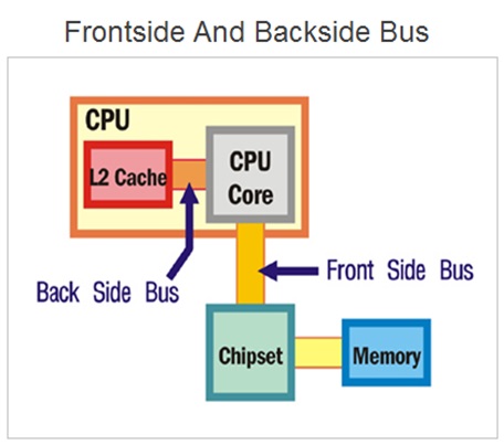
Front Side Bus
What is front side bus ( fsb ) .
The front side bus ( FSB ) represents one of the most important communication bus that connects some of the most vital components of the system. And hence , the FSB is also referred as system bus .
The front side bus connects the computers central processing unit ( CPU ) with the main system memory RAM . The FSB also connects PCI slots and DIMM slots on the motherboard with the processor socket .
And therefore , the FSB is an important communication bus that connects some of the most important components such as CPU , main memory RAM , graphics card and other components connected through PSI slots.
Chipset Architecture - Front Side Bus ( FSB )

These components are connected using the FSB through one of the memory controller chip called the north bridge . The motherboard chip set consist of two controller chips.
The front side bus is present on the motherboard embedded as a printed circuit board ( PCB ) wired connections running across the motherboard PCB .
The FSB speed is considered as an important parameter that significantly affect the CPU performance . The FSB speed is measured in Megahertz ( MHz ).
The FSB speed is generally ranges between 66 MHz to 800 Mhz. It can also be expressed as a ratio to CPU speed.
RAM Standards - Front Side Bus ( FSB ) Speed
The front side bus ( FSB ) is bi-directional bus . The FSB is used to by the CPU to either receive or send the data from various components connected to the CPU.
The CPU frequently communicates with system main memory RAM and other devices during the program execution. And therefore , the FSB speed matters for the CPU performance.
Join The Best Seller
Computer Science Online Course
Learn computer science and programming fundamentals.
This is the most comprehensive and unique Computer Science And Programming Fundamentals course Online which will give you in depth understanding of most important fundamental concepts in computer science And Programming .

Other Related Topics
Computer organization and architecture.

What Is Control Unit ?

What Is Central Processing Unit ?

What Are CPU Registers ?

Introduction To Computer System


Understanding Computer Bus: A Comprehensive Overview
As we move towards a technology-driven future, it is important to have an in-depth understanding of the components that make up our devices. One such component is the Computer Bus. In this post, we will take a comprehensive overview of what a computer bus is, its various components, and how it works. We will also delve into the different types of computer buses and their evolution over time. Understanding computer buses can be beneficial for IT professionals, programmers, and even casual users who want to optimize their system’s performance. So let’s dive in and explore the functions of a computer bus and why it plays such an important role in modern-day computing.
Table of Contents
Defining Computer Bus
A computer bus serves as a communication highway within a computer system, enabling efficient data exchange between various components, including the hard drive. It acts as a pathway for electrical signals to travel, allowing data transfer between the CPU, memory, and peripherals. The bus plays a crucial role in computer architecture, facilitating the exchange of data between different hardware components.
In a PC, there are different types of buses, such as the system bus, expansion bus, microcomputer bus, and memory bus. The system bus, also known as the motherboard bus or front-side bus (FSB), connects the CPU to the main memory. Expansion buses like PCI Express (PCIe) provide slots for various devices, such as graphics cards, sound cards, and network cards. The memory bus is responsible for connecting the CPU to the RAM.
Computer buses have evolved over time, from the early days of industry standard architecture (ISA) to modern high-speed buses like Peripheral Component Interconnect (PCI) Express. These buses have different features, including bus width and bus speed, which impact system performance.
To summarize, a computer bus enables efficient communication and data transfer within a computer system. It allows for the exchange of data between the CPU, memory, and peripherals, providing a vital pathway for electrical signals. Different types of buses serve various functions, ensuring smooth operation and connectivity between hardware components.
Breakdown of Components
The breakdown of components in a computer bus is essential for understanding the system. The data bus is responsible for transferring data between the CPU, memory, and peripherals, while the address bus determines the memory location of the accessed data. Additionally, the control bus coordinates and controls the activities of various components. Each component has a specific function within the computer bus, contributing to the exchange of data and ensuring efficient communication between different hardware devices. Understanding this breakdown is crucial for gaining a comprehensive understanding of the system. By grasping the roles and functions of the data bus, address bus, and control bus, users can navigate the complexities of computer architecture and optimize their system’s performance.
Data Bus, Address Bus, and Control Bus
The data bus, address bus, control bus, and local bus are essential components of a computer system. The data bus facilitates the exchange of data between the CPU, computer memory, and peripherals. It carries data in parallel, allowing for efficient and high-speed communication. On the other hand, the address bus determines the memory location of the data being accessed in computer memory. It carries memory addresses, enabling the system to locate the desired information. Lastly, the control bus coordinates and controls the activities of various components. It carries control signals that synchronize the communication within the system. The addition of the local bus to the computer system further enhances its functionality by providing a link between the CPU and other devices within the system. This allows for seamless communication and efficient data transfer, ensuring smooth operation of the computer system.
Together, these buses play a crucial role in enabling the exchange of data and instructions within a computer system. They ensure seamless communication between the different hardware components, allowing for the smooth operation of the system. By understanding the functions and operations of the data bus, address bus, and control bus, one can gain a comprehensive understanding of how information flows within a computer system.
Detailed View of Bus Architecture
Bus architecture plays a crucial role in how components within a computer system are connected and communicate with each other. Different types of buses serve specific purposes, such as the system bus, expansion bus, and memory bus. The architecture of these buses greatly affects the overall performance and scalability of the system. By ensuring efficient data exchange, proper bus architecture enables smooth operation and enhances system functionality.
Understanding the intricacies of bus architecture is essential for designing computer systems that meet specific requirements. It involves comprehending the various components involved, including the motherboard, RAM, PCI Express, microprocessor, and the central processing unit (CPU). Additionally, other devices like graphics cards, storage drives, and peripherals also rely on the bus architecture for seamless communication.
In conclusion, a detailed view of bus architecture is vital for developers, system designers, and engineers alike. By grasping the underlying principles and utilizing appropriate bus configurations, they can create efficient and reliable computer systems. This understanding empowers them to make informed decisions regarding the selection and implementation of various buses and components.
Role of Bus Width and Bus Speed
The role of bus width and bus speed is crucial in determining the efficiency of data transfer within a computer system. Bus width refers to the number of bits that can be transferred at once, and a wider bus allows for faster data transfer. On the other hand, bus speed refers to the rate at which data is transferred. Higher bus speeds result in faster data exchange between components.
Both bus width and bus speed play a significant role in system performance. A wider bus, such as a 32-bit address bus, allows more data to be transferred simultaneously, reducing the time required for communication between different components such as the CPU, memory, and peripherals. Similarly, a higher bus speed facilitates faster data transfer, enabling smoother operation and improved overall system performance.
In summary, the bus width and bus speed directly impact the efficiency and speed of data exchange within a computer system. Maximizing both parameters is essential for achieving optimal performance and ensuring smooth operation of various devices and components.
Types of Computer Buses
Internal and external buses are two key types of computer buses that serve different communication needs within a system. Internal buses connect components within the CPU and memory, facilitating efficient data transfer and coordination. On the other hand, external buses connect the CPU and memory to peripherals such as input/output devices and storage devices.
Both internal and external buses play a vital role in enabling the exchange of data between various devices and components. They work together to ensure seamless communication within the system architecture. Understanding the types of computer buses is crucial for system design, as it allows for the selection and configuration of the appropriate bus types based on the specific requirements of the system.
By choosing the right combination of internal and external buses, system designers can optimize data transfer speeds and improve overall system performance. The integration of different types of buses, such as the Intel Dual Independent Bus (DIB), ensures the smooth functioning and coordination of various hardware components, such as the central processing units (CPUs), main memory (RAM), graphics card, and other peripherals.
In summary, comprehending the types of computer buses is essential for system designers and architects as it allows for the efficient exchange of data and the proper functioning of a computer system.
Internal Buses vs External Buses
Internal buses and external buses are two types of computer buses that play different roles in system communication. Internal buses connect components within the CPU and memory, allowing for fast data transfer between these vital parts of the system. With a shorter distance to travel, internal buses facilitate quicker communication and enhance overall system performance.
On the other hand, external buses connect the CPU and memory to peripherals, enabling data exchange with external devices such as printers, keyboards, and storage devices. These buses provide the necessary link for interaction with various devices outside the main system.
Both internal and external buses are crucial for system functionality. While internal buses optimize communication within the CPU and memory, external buses broaden system capabilities by facilitating the exchange of data with peripheral devices. Together, they form an essential part of computer architecture, ensuring efficient and seamless operation of the system.
In summary, understanding the differences between internal and external buses is key to comprehending the intricate workings of a computer system. The unique roles these buses play in connecting and enabling the exchange of data between different components and peripherals highlight their significance in computer hardware design and performance optimization.
Evolution of Computer Buses
Computer buses have undergone significant evolution from their first generation to the modern day. Advancements in technology have paved the way for faster and more efficient bus designs, offering higher speeds and increased bandwidth. Understanding the evolution of computer buses is crucial as it provides valuable insights into system development. The evolution of computer buses has revolutionized computing capabilities, enabling the exchange of data between various devices seamlessly. From the early days of the IBM PC and ISA buses to the introduction of PCI Express and PCIe, computer architecture has evolved tremendously. Buses such as FSB, AGP, and NUBUS have played a vital role in connecting different components like the CPU, main memory, and peripherals. The constant innovation in bus design and the introduction of new standards like HyperTransport and ExpressCard have further improved the performance of computer systems. The exchange of data through electrical wires and the coordination of different buses by the chipset contribute to the overall functionality of a computer system. In conclusion, the evolution of computer buses has shaped the landscape of computer hardware, allowing for faster, more efficient, and interconnected systems.
From First Generation to Modern Day
First-generation computer buses, such as the S-100 bus, were characterized by their simplicity and slow data transfer rates. However, advancements in bus technology have led to significant improvements in terms of speed and performance. Modern computer buses utilize advanced protocols, offering high-speed data transfer and enhanced system capabilities. The evolution of computer buses has played a crucial role in technological advancements, enabling the exchange of data between various devices with greater efficiency. From humble beginnings, computer bus technology has come a long way, shaping the landscape of computer architecture and revolutionizing the capabilities of modern PCs. Today, computer buses such as the Peripheral Component Interconnect Express (PCIe) and the Front-Side Bus (FSB) have become integral components of a computer’s motherboard, facilitating the seamless communication between the Central Processing Unit (CPU), RAM, and other peripherals. The continuous progress in computer bus technology, including the use of backplane, has paved the way for faster and more efficient computing systems, empowering users to accomplish complex tasks with ease.
What are the functions of a Computer Bus?
Computer buses serve multiple functions in a computer system. They enable communication between components, facilitate data transfer between the CPU, memory, and peripherals, coordinate and control component activities, determine memory addresses for data access, and ensure proper system functionality.
Importance of Bus in System Performance
A computer system’s performance is determined by the efficiency of its components, and the bus plays a crucial role in this regard. An optimized bus architecture can significantly improve data transfer speeds, ensuring that the system operates smoothly and efficiently. By connecting various components such as the CPU, memory, and peripherals, the bus enables seamless communication and the sharing of information. This efficient exchange of data minimizes latency and bottlenecks, resulting in faster data processing. The speed and bandwidth of the bus directly impact the system’s ability to handle demanding tasks, making it a vital component for high-performance computing. A well-designed bus design ensures that the system can handle complex operations without compromising on speed or efficiency. In conclusion, the bus’s importance in system performance cannot be overstated, making it an essential consideration in computer architecture.
Frequently Asked Questions
What is a computer bus and how does it work.
A computer bus is a communication system responsible for transferring data between various components of a computer, including a video card. It works by transmitting signals through wires or traces on a circuit board. The bus architecture determines the speed, bandwidth, and compatibility of the components. Common types of computer buses include PCI, USB, SATA, and Ethernet.
What are the different types of computer buses?
Various types of computer buses play crucial roles in connecting internal and external components. Some common examples include PCI, USB, SATA, SCSI, and Ethernet. The Peripheral Component Interconnect (PCI) bus is used internally, while the Universal Serial Bus (USB) connects external devices like keyboards and printers. Serial ATA (SATA) is utilized for high-speed data transfer among storage devices. The Small Computer System Interface (SCSI) is another type of bus commonly used for printer or hard drive devices, providing advanced technology attachment. Additionally, the FireWire bus, also known as IEEE 1394, is used for connecting devices, keyboards, or modem devices in a daisy-chain topology or hub design.
How do computer buses affect the performance of a computer system?
Computer buses play a crucial role in the performance of a computer system. The speed and bandwidth of the bus can affect how fast data is transferred between components, which can in turn affect system performance. A bottleneck in the bus can slow down the entire system. Upgrading to a faster bus or optimizing the current bus can improve overall system performance.
How can I troubleshoot issues related to computer buses?
To troubleshoot issues related to computer buses, start by checking for loose connections or cables that may be causing communication errors. You can also use diagnostic software to identify any hardware or software issues with the bus. Updating drivers and firmware can help ensure compatibility. If all else fails, consider replacing faulty hardware components.
Are there any common issues or problems associated with computer buses?
Common issues with computer buses can include data transfer errors, compatibility issues, and electrical failures. Troubleshooting problems may involve checking connections, updating drivers, and testing components. Symptoms of bus-related issues can include slow performance, system crashes, and error messages. Regular maintenance and updates can help prevent problems and ensure optimal performance.
To summarize, computer buses play a crucial role in the functioning and performance of a computer system. They serve as the communication channels between various components, facilitating the transfer of data, addresses, and control signals. The width and speed of the bus are key factors in determining the overall system performance. Over the years, computer buses have evolved significantly, from the early days of simple buses to the complex and high-speed buses used in modern systems. Understanding the functions and types of computer buses is essential for anyone interested in computer architecture. By delving deeper into this topic, you can gain a comprehensive overview of how computers communicate internally and optimize their performance.
References:
https://doi.org/10.1109%2F85.194088
https://doi.org/10.1109%2FCMPCON.1990.63672
Leave a Comment Cancel Reply
Your email address will not be published. Required fields are marked *
Save my name, email, and website in this browser for the next time I comment.
- Engineering Mathematics
- Discrete Mathematics
- Operating System
- Computer Networks
- Digital Logic and Design
- C Programming
- Data Structures
- Theory of Computation
- Compiler Design
- Computer Org and Architecture
Computer Organization and Architecture Tutorial
In this Computer Organization and Architecture Tutorial, you’ll learn all the basic to advanced concepts like pipelining, microprogrammed control, computer architecture, instruction design, and format.
Computer Organization and Architecture is used to design computer systems. Computer Architecture is considered to be those attributes of a system that are visible to the user like addressing techniques, instruction sets, and bits used for data, and have a direct impact on the logic execution of a program, It defines the system in an abstract manner, It deals with What does the system do.
Whereas, Computer Organization is the way in which a system has to structure and It is operational units and the interconnections between them that achieve the architectural specifications, It is the realization of the abstract model, and It deals with How to implement the system.
Table of Content
- Basic Computer Instructions :
- Instruction Design and Format :
- Computer Arithmetic :
- Microprogrammed Control :
- Memory Organization :
- Input and Output Systems :
- Pipelining :
- IEEE Number Statndards
- Miscellaneous :
- Quick Links :
To deepen your knowledge in Computer Organization and Architecture and prepare for exams like GATE, consider enrolling in the GATE CS Self-Paced course . This course offers detailed coverage of essential topics, helping you build a solid foundation in computer science and achieve your academic and career goals.
- Basic Computer Instructions
- A simple understanding of Computer
- Issues in Computer Design
- Computer System Level Hierarchy
- Computer Architecture and Computer Organization
- Timing diagram of MOV Instruction in Microprocessor
- Assembly language and High level language
- Addressing Modes
- Memory based Vs Register based addressing modes
- Von Neumann architecture
- Harvard Architecture
- Interaction of a Program with Hardware
- Simplified Instructional Computer (SIC)
- Instruction Set used in simplified instructional Computer (SIC)
- Instruction Set used in SIC/XE
- RISC and CISC
- RISC and CISC | Set 2
- Vector processor classification
- Essential Registers for Instruction Execution
- Single Accumulator based CPU organization
- Stack based CPU Organization
- General Register based CPU Organization
- Data Transfer instructions in AVR microcontroller
- Arithmetic instructions in AVR microcontroller
- Conditional Branch Instructions in AVR Microcontroller
- CALL Instructions and Stack in AVR Microcontroller
- Branch Instructions in AVR Microcontroller
- Logical Instructions in AVR Microcontroller
- Data Manipulation Instructions
- Machine Control Instruction
- Very Long Instruction Word (VLIW) Architecture
Instruction Design and Format
- Different Instruction Cycles
- Machine Instructions
- Instruction Formats (Zero, One, Two and Three Address Instruction)
- 2-address instruction and 1-address instructions
- 3-address instruction and 0-address instruction
- 3-address instruction and 2-address instructions
- Register content and Flag status after Instructions
- Debugging a machine level program
- Vector Instruction Format
- Vector instruction types
- Branch Prediction in Pentium
- Instruction Word Size
- >> Problem Solving on Instruction Format
Computer Arithmetic
- Computer Arithmetic | ALU and Data Path
- Computer Arithmetic | Set 1
- Computer Arithmetic | Set 2
- Difference between 1’s complement and 2’s complement
- Restoring Division Algorithm For Unsigned Integer
- Non-Restoring Division For Unsigned Integer
- Booth’s Algorithm
- Overflow in Arithmetic Addition
- How the negative numbers are stored in memory?
- Conventional Computing vs Quantum Computing
Quiz on Number Representation
Microprogrammed Control
- Micro-Operation
- Microarchitecture and Instruction Set Architecture
- Types of Program Control Instructions
- Difference between CALL and JUMP instructions
- Hardwired v/s Micro-programmed Control Unit
- Implementation of Micro Instructions Sequencer
- Performance of Computer
- Control Unit and design
- Horizontal micro-programmed Vs Vertical micro-programmed control unit
- Camparisons between Hardwired Vs Micro-programmed Control unit
- Computer Organization | Subprogram and its characteristics
Memory Organization
- Introduction to memory and memory units
- Memory Hierarchy Design and its Characteristics
- Difference between Byte Addressable Memory and Word Addressable Memory
- Difference between Simultaneous and Hierarchical Access Memory Organisations
- Register Allocation
- Cache Memory
- Cache Organization | Set 1 (Introduction)
- Multilevel Cache Organisation
- Locality and Cache friendly code
- Locality of Reference and Cache Operation
- Amdahl’s law and its proof
- Subroutine, Subroutine nesting and Stack memory
- What’s difference between CPU Cache and TLB?
- Different Types of RAM
- Types of computer memory (RAM and ROM)
- Secondary memory – Hard disk drive
- Introduction to solid-state drive (SSD)
- Read and Write operations in memory
- 2D and 2.5D Memory organization
Input and Output Systems
- Priority Interrupts | (S/W Polling and Daisy Chaining)
- I/O Interface (Interrupt and DMA Mode)
- Direct memory access with DMA controller 8257/8237
- Asynchronous input output synchronization
- Programmable peripheral interface 8255
- Interface 8255 with 8085 microprocessor for 1’s and 2’s complement of a number
- 8255 (programmable peripheral interface)
- Microcomputer system
- Working of 8085-based Single board microcomputer
- Interface 8254 PIT with 8085 microprocessor
- Synchronous Data Transfer
- Input-Output Processor
- MPU Communication
- Memory mapped I/O and Isolated I/O
- BUS Arbitration
- Instruction Level Parallelism
- Execution, Stages and Throughput
- Types and Stalling
- Dependencies and Data Hazard
IEEE Number Standards
- IEEE Standard 754 Floating Point Numbers
Miscellaneous
- Microprocessor
- Microprocessor | Externally Initiated Operations
- Bus organization of 8085 microprocessor
- Generations of computer
- Intel x86 evolution and main features
- Memory Banking
- Introduction to quantum computing
- Rethinking binary with Quantum computers
- Flynn’s taxonomy
- Clusters In Computer Organisation
- Parallel processing – systolic arrays
- 8259 PIC Microprocessor
- Block Diagram of 8259 Microprocessor
- Microprocessor | 8251 USART
- Evolution of Microprocessors
- Human – Computer interaction through the ages
- Computer Ports
- Introduction to Parallel Computing
- Hardware architecture (parallel computing)
- Computer Architecture | Multiprocessor and Multicomputer
- Timing diagram of INR M
- Program for Binary To Decimal Conversion
- Program for Decimal to Binary Conversion
- Program for decimal to octal conversion
- Program for octal to decimal conversion
- Program for hexadecimal to decimal
Quick Links
- ‘Quizzes’ on Computer Organization and Architecture !
- ‘Practice Problems’ on Computer Organization and Architecture !
Computer Organization and Architecture Tutorial – FAQs
What is computer organization.
Computer organization refers to the operational units and their interconnections that realize the architectural specifications of a computer. It involves the structural relations and the manner in which the components of the computer system are connected and work together.
What is computer architecture?
Computer architecture is the conceptual design and fundamental operational structure of a computer system. It encompasses the layout of the hardware, the design of the instruction set, and the techniques for data handling and processing. The objective is to outline a blueprint that ensures optimal performance and efficiency.
What is the difference between computer organization and architecture?
While computer architecture is concerned with the conceptual design and functional specification of a computer system, computer organization deals with the detailed operational implementation of the system. Essentially, architecture provides the macro-level blueprint, while organization focuses on the micro-level realization.
Why is understanding computer organization and architecture important?
Understanding computer organization and architecture is crucial for designing efficient computer systems, improving existing ones, and making informed decisions about hardware resources. It also helps in optimizing software to make full use of the underlying hardware and enhance overall system performance.
What are the key components of computer organization?
The key components of computer organization include the central processing unit (CPU), memory hierarchy (registers, cache, RAM, and secondary storage), input/output devices, and the interconnection system (buses and communication channels) that allows these components to interact effectively.
this Computer Organization and Architecture Tutorial has covered the fundamental concepts essential for understanding how computer systems function. From the basic building blocks like registers and ALUs to complex concepts such as pipelining and memory hierarchies, you now have a solid foundation. This knowledge is crucial for anyone pursuing a career in computer science or related fields. Keep exploring and practicing these concepts to deepen your understanding and stay updated with the latest advancements in computer architecture. This tutorial is just the beginning of your journey into the fascinating world of computer systems.
Please Login to comment...
Similar reads.
- Computer Organization and Architecture
- How to Watch NFL Games Live Streams Free
- OpenAI o1 AI Model Launched: Explore o1-Preview, o1-Mini, Pricing & Comparison
- How to Merge Cells in Google Sheets: Step by Step Guide
- How to Lock Cells in Google Sheets : Step by Step Guide
- #geekstreak2024 – 21 Days POTD Challenge Powered By Deutsche Bank
Improve your Coding Skills with Practice
What kind of Experience do you want to share?
TechRepublic
Account information, share with your friends.
Understanding your motherboard’s bus system
Your email has been sent

These days, pick up any electronic device and you’ll find some acronyms on the box describing the various busses it supports. A computer will have a list of busses as long as your arm. In this Daily Drill Down, I’ll discuss the different busses currently available and in use to help you understand exactly what your equipment is capable of.
What’s a bus? A bus is the path through which a device sends its data so that it can communicate with the CPU and/or other devices. For example, a PCI device, such as an audio card, will send its data through the PCI bus. Each device will have an access point to the bus using a particular kind of interface. The word interface refers not only to the physical port the devices plug into, but to the electrical operating parameters and the communication format as well. Typically, each bus has a uniquely shaped interface to prevent you from damaging your devices by plugging them into the wrong ports. PCs have three or more busses.
The motherboard’s bus system has been compared to a mass transit system that carries data over many routes through the city (your motherboard) and uses different types of vehicles (fast and slow, and small and large) to carry it.
The differences between computer busses break down into these categories:
- Device management
The data width and cycle rate are used to determine the bandwidth, or the total amount of data that the bus can transmit. An 8-bit bus (1-byte data width) that operates at a cycle rate of 1,000 MHz (1,000,000 times per second) can transfer 8 Mbps (1 MBps).
The device-management specification indicates the maximum number of supported devices and the difficulty of configuring them. There are two types of bus communications, serial and parallel. On a parallel bus, all devices have their own interface to the bus, which is the norm. Serial devices are tied together in, well, a series; the last one has to talk “through” the first one. This can cause obvious performance problems. These busses typically are used in conditions where data throughput isn’t critical.
Front Side Bus (FSB) The Front Side Bus is the interface between the CPU and the motherboard, specifically the North Bridge/Memory Controller Hub. See below for details on the FSBs in use by Intel and AMD. For more information on this subject, see my Daily Drill Down, “ Motherboard chipsets—the good, the bad, and the ugly .”
Intel GTL+ Front Side Bus At the simplest level, Intel’s GTL+ FSB provides a single connection to the North Bridge shared between all CPUs. In a dual-CPU system, this halves the available bandwidth and quarters it for a quad CPU board. Someone is sure to point out the fact that CPUs almost never need the full bandwidth of the bus. Quite true. Unfortunately, since the bus is in an all-or-nothing situation, the CPUs must take turns. (Hello Mr. Latency, care to have a seat and chat while we’re waiting for the bus to arrive?) The problem is even worse in today’s world of 800-MHz CPUs running on 133-MHz memory where even a single CPU has to wait up to six processor cycles for a data request. Imagine a quad CPU server being used for something other than show; if the application isn’t smart enough to fill that L1 cache, or—heaven forbid—your L1 cache is too small to last the duration, you’ll have processors sitting idle. So you might as well use fewer or slower CPUs and save some cash. This is why only Intel’s Xeon processors, coming with up to eight times as much L1 cache as a Pentium III, are usable in systems with more than two processors.
AMD EV-6 Front Side Bus The EV-6 FSB is more like a network switch than a bus, since each processor has a full connection to the North Bridge running at an effective 200 MHz; 50 percent faster than Intel’s 133-MHz FSB. Between per-processor links to the North Bridge and that high-speed bus, the EV-6 is an excellent multiprocessor bus. Naturally, the total effective CPU bandwidth can’t exceed the bandwidth available from the other interfaces combined, but unlike the GTL+ bus, one CPU could access peripherals on the PCI bus while another accesses memory.
Of course, the EV-6 bus is nothing new to the computing world since it was one of Alpha’s weapons in the server wars. This is also academic until AMD releases the multiprocessor version of the 760 chipset in late December 2000.
Memory busses The memory bus is the interface between the RAM and the motherboard. Because each variant requires a different type of controller, few motherboards support more than one type of memory. There have been many forms of memory that are now considered obsolete. The current types are discussed below.
DDR-SDRAM (Double Data Rate Synchronous Dynamic Random Access Memory) This upcoming replacement for SDRAM is basically the same product, but it operates twice per clock cycle. Two grades are expected to be introduced initially: the 2x 100-MHz PC1600 (1.6 GBps) and the 2x 133-MHz PC2100 (2.1 GBps). DDR-SDRAM is only about 10 to 20 percent more expensive than traditional SDRAM and provides better performance than single-channel RDRAM. A 2x 200-MHz PC3200 (3.2 GBps) is currently under development that will provide the same performance level of dual-channel RDRAM while using only a single memory module.
RDRAM (Rambus Dynamic Random Access Memory) Rambus is a proprietary memory architecture being touted by Intel. It has a serial memory format with a very narrow 16-bit interface but operates very fast at 800 MHz on a DDR-type 400-MHz bus, resulting in 1.6 GBps of bandwidth. A dual-channel RDRAM system is used on a rare few workstation systems: It has two RDRAM controllers for 3.2 GBps of bandwidth but requires the RDRAM to be installed in pairs.
RDRAM is several times more expensive than SDRAM and provides increased latency. It will shortly be challenged by DDR-SDRAM in the marketplace on both price and performance.
SDRAM (Synchronous Dynamic Random Access Memory) SDRAM is the standard memory format for the majority of computers on the market. This 64-bit memory comes in three grades: PC66 (66 MHz or 528 MBps), PC100 (100 MHz or 800 MBps), and PC133 (133 MHz or 1.06 GBps). PC66 was used on early Intel Pentium IIs and all Intel Celeron PCs. PC100 is in use on the vast majority of Intel Pentium II and Pentium III processors. PC133 is the preferred memory of all AMD Athlon and Duron processors and the latest Pentium III systems.
VCM (Virtual Channel Memory) This subset of SDRAM is a low-latency variant that provides increased performance. It runs at 133 MHz and has the same 1 GB of bandwidth as PC133 SDRAM but shaves off about 10 nanoseconds of latency from SDRAM’s normal 40-nanosecond latency. It does this by using special “fast” registers that keep track of memory pages. These registers provide a fast link, or channel, to the memory used by an application. VCM actually works better for complex applications like games and databases that have memory spanning multiple memory banks.
VCM is supported on a number of Pentium II, Pentium III, and Athlon motherboards but is very difficult to acquire. The low production volumes have kept prices out of proportion to the performance compared to standard PC133. Motherboards that support VCM can use it or standard SDRAM.
High-speed I/O busses Now let’s take a look at the high-speed I/O busses.
AGP/Pro (Advanced Graphics Port) This interface is a 32-bit system based on the PCI standard, revision 2.1. The initial version, 1x, operated at 66 MHz for 266 MBps with direct memory-access abilities that PCI didn’t have. The 2x variant is a double-data-rate system that transmits data twice per clock cycle, for a functional frequency of 133 MHz (532 MBps).
The 4x again doubles the bandwidth up to 1,066 MBps and has additional memory-access features. The bandwidth of AGP 4x is greater than SDRAM’s abilities, making most of the improvements of only limited use on systems not currently using Rambus RDRAM (1.6 GBps) or the upcoming double-data-rate DDR memory (2.1 GBps).
The Pro is a 4x variant that includes additional power leads to run today’s high-transistor-count video cards. Standard AGP slots provide up to 25 watts of power, far less than AGP Pro’s maximum available 110 watts.
The AGP port is typically a dark-colored port that resembles a PCI slot. It’s set farther back from the edge of the motherboard than the PCI slots and is located near the power supply and processor on most boards.
EIDE (Enhanced Integrated Drive Electronics) IDE hard drives include a device controller mounted on the drive, the result of a 1986 collaboration between Compaq and Western Digital to develop a cheap drive with good performance. They decided to limit the number of pins and the cable length as it was intended for lower-end systems that would not need a large number of internal devices.
Because each device has its own controller, only two devices can be on each chain to prevent excess interference. Modern IDE host adapters can operate two chains, each with a master and a slave. The master can interrupt the slave device at any time, making it inappropriate for the primary system drive or sensitive devices like CD-R, CD-RW, and tape drives to be slaves. The maximum of four devices per controller (two chains with two devices each) limits the number of devices an IDE system can handle.
The current generation of integrated IDE host adapters requires some management by the computer’s processor, creating a load on the system. The various implementations of direct memory access (DMA) protocols helped transfer data to the computer’s RAM from devices with less management by the processor. Transfer rates increased under the ATA-2 specification from 11.1 MBps to 16.66 MBps—a significant increase but still a bottleneck for PCs. Beginning with ATA-2 (also known as Fast ATA), the improved interface became known as EIDE, rather than IDE.
In 1996, the ATA/33 specification utilized newer DMA techniques to reach 33-MBps transfer rates. Also known as Ultra DMA or UDMA/33, it was completely backward-compatible with previous devices and became the standard for PC hard drives.
The year 1999 saw the introduction of the improved ATA/66 format. The 66-MBps system relies on a 40-pin cable with a similar connector to previous IDE formats, but it uses 80 conductors to ensure signaling. To operate at 66 MBps, only ATA/66 devices can exist on a channel. The controller can still operate earlier IDE devices, but the existence of non-ATA/66 devices forces a channel to drop down to ATA/33 speeds. ATA/66 has been widely adopted and is standard on many new computers.
Earlier this year, ATA/100 was introduced. Initial products were sometimes called ATA/66+. It continues the use of the 80-conductor cable and provides transfer rates up to 100 MBps. IDE devices are quite inexpensive, and due to the improved DMA functions, they do not impact system performance as much as in the past. IDE drives can be used in a RAID configuration with a four-drive limit imposed by the controller cards. A sufficiently complex controller could operate multiple IDE channels for more drives.
EISA (Extended Industry Standard Architecture) The ISA bus was the first widespread PC interface, introduced by IBM on the AT computer as the system bus. It was at first an 8-bit bus that ran at 8 MHz (8 MB/second of bandwidth) that was quickly upgraded to a 16-bit bus (16 MBps). It utilizes interrupts, the digital equivalent of a wake-up call, to manage the devices. The interrupts (referred to as IRQs) are hardwired to the ports on the motherboard and cannot be reallocated. Communication occurs using I/O and memory addresses that can be reallocated among the ports. To function, each device must have the IRQ, I/O, and memory addresses configured properly at boot.
ISA was later extended to a 32-bit wide bus operating at 8 MHz (32 MBps) and renamed the Extended Industry Architecture (EISA) bus. ISA devices would work in an EISA motherboard to ensure compatibility. EISA added more I/O and memory access channels, allowed sharing IRQs, and enabled software to configure cards.
EISA devices plug directly onto the motherboard using the long, typically dark-colored slots located at the farthest edge of the board. ISA has been obsolete for several years and EISA is slowly dying out. Current motherboards have no more than one to three EISA slots. A large number of motherboards are completely devoid of EISA support.
FireWire/IEEE 1394 Developed by Apple and ratified by the IEEE (a subset of ANSI, the organization that also ratifies SCSI and IDE), FireWire is high-bandwidth, hot-swappable interface that supports up to 63 devices at a transfer rate of 50 MBps. It has not been widely accepted because it competes with SCSI, a highly established interface. Because it is a high-performance design for portable devices, it suffers from low initial sales volumes that prevent it from competing with SCSI on the merits of price the way IDE can.
PC-Card/PCMCIA (Personal Computer Memory Card International Association) The PCMCIA group that defines this standard originally designated the devices as PCMCIA cards. Most people called them laptop cards, or those PC-something-something cards, which impelled the devices to be dubbed PC-Cards and the bus simply CardBus.
There are three types of PC-Cards, all of them slightly larger than a credit card. Type 1 is only 3.3 mm high and typically only suitable for memory devices. Type 2 cards, at 5 mm high, are large enough to support modems, network cards, and other interface devices. The large 10 mm Type 3 cards enable hard drives and other large storage devices.
The data throughput varies from 4 MBps for the slowest 16-bit data transfers to 132 MBps in the fastest 32-bit mode, as defined by the device.
PCI (Peripheral Component Interconnect) PCI replaced EISA as the system bus of PC computers. It includes a Bridge chip that enables other types of processors to communicate with it. As a result, PCI is a standard bus on PCs and on Macintosh, Sun, and Alpha machines. The desktop variant of PCI is a 32-bit bus operating at 33 MHz (133 MBps). The PCI standard supports a 64-bit (266-MBps) variant. However, this format is currently in use only by workstation and server manufacturers like Sun or Compaq/DEC. The current plan is for PCI to skip the long-proposed 66-MHz PC and evolve into PCI X (eXtended), a 133-MHz (532-MBps) version with essentially the same features but triple the bandwidth.
PCI is intended to be Plug and Play capable, using software to configure the boards like EISA. It also supports a much larger number of I/O and memory addresses and uses better direct memory access than EISA. PCI is bus mastered, meaning that all devices can talk to each other without CPU intervention, which increases system performance.
PCI slots are white and much shorter than EISA slots. Most boards will have between three and five PCI slots.
SCSI (Small Computer System Interface) A high-performance device interface, SCSI was introduced in the mid-1980s to compete with the now-obsolete ESDI device interface. SCSI was targeted for PCs, Apple Macintosh, UNIX workstations, and minicomputers but not mainframes, hence the “small” designation. SCSI was designed from the beginning to support not only hard drives but also scanners, optical drives, and other high-capacity/high-bandwidth devices that are not necessarily mounted inside the computer.
There are several generations of SCSI that in many cases have a “wide” 16-bit version and a “narrow” 8-bit version. The performance of SCSI ranges from the 5 MBps of SCSI-1 to the upcoming Ultra 320 (320-MBps) system. For more information, read TechProGuild’s “ A SCSI primer: Seven generations of high-performance hardware ,” and “ SCSI, IDE, and FireWire specs at a glance .”
USB (Universal Serial Bus) USB can handle up to 128 devices. The devices are hot-swappable, meaning that they can be added and removed while the computer is operating. Thus, this bus is very handy for portable devices. USB provides power to devices through the interface, enabling ultralight and convenient accessories free of power cables or cords. The power supply is finite, but a powered hub or other self-powered device will increase the possible number of bus-powered devices.
The total bandwidth of USB is 1.5 MBps; this bandwidth is shared between all the devices on the controller. Because it is a serial bus, USB devices are daisy chained. USB supports hubs that can connect multiple devices, which cuts down the number of devices between the controller and the end of the line, but since each hub counts as a device, this solution reduces the total that can be supported. Of course, with USB’s low bandwidth, it isn’t really feasible to utilize all 128 devices.
USB 2.0 has been in development for a while and is supposed to be a 60-MBps bus. This bandwidth is enough to operate a hard drive, 100-Mb Ethernet, or video-capture system with plenty of overhead left over for mice, keyboards, and other high-urgency devices.
Low-speed I/O busses The following sections discuss the low-speed I/O busses.
Parallel port This 25-pin port should be familiar to everyone with a printer or a Zip drive. It originally had a maximum transfer rate of 115 KBps, suitable for line printers and 1980s devices. Then came enhanced ECP/EPP control logic that boosted transfer rates to 3 MBps, a needed increase to support high-speed graphical printers.
The parallel port is technically an interface rather than a bus, but because of the recent proliferation of “pass-through” devices like Zip drives that allow serial-type bus activity, it is included in this section. Parallel is still the most widely supported high-bandwidth external device interface on the market, and it will likely be around for many years to come.
PS/2 port IBM introduced the familiar, round PS/2 port to connect keyboards and mice. It is an ultralow bandwidth interface that will remain the standard until operating systems can reliably support USB keyboards and mice.
Serial port This 15-pin, 115-KBps port is now used primarily for modems and personal digital assistants. It was once the primary port for mice but has been supplanted by the PS/2 port. Virtually all computers have a serial port on the back. As with parallel ports, the serial port is technically an interface rather than a bus. However, because of the recent proliferation of “pass-through” devices like PDAs that allow serial-type bus activity, it is also included in this section.
Special motherboard connectors Now let’s look at other types of motherboard connectors.
ACR (Audio Communication Riser) Risers are so named because they rise above the motherboard, either parallel or perpendicular to it. The ACR hardware standard is an attempt to replace the poorly received AMR (Audio Modem Riser) and CNR (Communication Network Riser) formats. The interface is a PCI port but with different pin-outs, and it is compatible with the older AMR system. It appears identical to a PCI slot and is typically placed at an angle to the other slots on a motherboard.
AMR (Audio Modem Riser) This Intel-designed expansion port is intended for mass manufacturers to use to add either a modem or audio card that relies on the CPU for much of its processing power. It is a very small slot; about half the length of a PCI slot. AMR is being replaced by CNR.
CNR (Communication Network Riser) CNR expansion ports are intended for use by mass manufacturers to slot into the motherboard either a low-cost network card, modem, or audio card that relies on the CPU for much of its processing power. The riser uses a very short slot; half as long as a PCI slot. CNR replaces AMR.
Conclusion New developments in bus speeds free up system bottlenecks, letting devices keep up with faster CPUs. Keep in mind the information in this Daily Drill Down, and you can determine which busses suit your needs and which ones will soon become obsolete. The authors and editors have taken care in preparation of the content contained herein but make no expressed or implied warranty of any kind and assume no responsibility for errors or omissions. No liability is assumed for any damages. Always have a verified backup before making any changes.
Subscribe to the Data Insider Newsletter
Learn the latest news and best practices about data science, big data analytics, artificial intelligence, data security, and more. Delivered Mondays and Thursdays

Create a TechRepublic Account
Get the web's best business technology news, tutorials, reviews, trends, and analysis—in your inbox. Let's start with the basics.
* - indicates required fields
Sign in to TechRepublic
Lost your password? Request a new password
Reset Password
Please enter your email adress. You will receive an email message with instructions on how to reset your password.
Check your email for a password reset link. If you didn't receive an email don't forgot to check your spam folder, otherwise contact support .
Welcome. Tell us a little bit about you.
This will help us provide you with customized content.
Want to receive more TechRepublic news?
You're all set.
Thanks for signing up! Keep an eye out for a confirmation email from our team. To ensure any newsletters you subscribed to hit your inbox, make sure to add [email protected] to your contacts list.
IEEE Account
- Change Username/Password
- Update Address
Purchase Details
- Payment Options
- Order History
- View Purchased Documents
Profile Information
- Communications Preferences
- Profession and Education
- Technical Interests
- US & Canada: +1 800 678 4333
- Worldwide: +1 732 981 0060
- Contact & Support
- About IEEE Xplore
- Accessibility
- Terms of Use
- Nondiscrimination Policy
- Privacy & Opting Out of Cookies
A not-for-profit organization, IEEE is the world's largest technical professional organization dedicated to advancing technology for the benefit of humanity. © Copyright 2024 IEEE - All rights reserved. Use of this web site signifies your agreement to the terms and conditions.
An optimal algorithm for layer assignment of bus escape routing on PCBs
New citation alert added.
This alert has been successfully added and will be sent to:
You will be notified whenever a record that you have chosen has been cited.
To manage your alert preferences, click on the button below.
New Citation Alert!
Please log in to your account
Information & Contributors
Bibliometrics & citations.
- Lin D Chen C Wei R Liu Q He H Zhu Z Lin Z Chen J (2024) Two stage ordered escape routing combined with LP and heuristic algorithm for large scaled PCB Integration 10.1016/j.vlsi.2024.102270 (102270) Online publication date: Sep-2024 https://doi.org/10.1016/j.vlsi.2024.102270
- Wen H Cai Y Hsu Y Chang Y (2022) Via-Based Redistribution Layer Routing for InFO Packages With Irregular Pad Structures IEEE Transactions on Computer-Aided Design of Integrated Circuits and Systems 10.1109/TCAD.2022.3155069 41 :12 (5554-5567) Online publication date: Dec-2022 https://doi.org/10.1109/TCAD.2022.3155069
- Chen J Liu J Chen G Zheng D Young E (2019) MARCH Proceedings of the 56th Annual Design Automation Conference 2019 10.1145/3316781.3317860 (1-6) Online publication date: 2-Jun-2019 https://dl.acm.org/doi/10.1145/3316781.3317860
- Show More Cited By
Index Terms
Electronic design automation
Physical design (EDA)
Recommendations
New optimal layer assignment for bus-oriented escape routing.
In this paper, based on the optimal feature of a left-edge algorithm for interval packing, a modified left-edge algorithm is proposed to optimally solve the layer assignment problem for bus-oriented escape routing. Firstly, a set of assignment ...
It is known that the increase of the pin count makes escape routing difficult in PCB designs. Based on the optimal feature of a left-edge algorithm for interval packing, a modified left-edge algorithm is proposed to optimally solve the layer assignment ...
Optimal layer assignment for escape routing of buses
Escape routing is a critical problem in PCB design. In IC-CAD'07, a layer assignment algorithm was proposed for escape routing of buses. The algorithm is optimal for single layer design in the sense that it determines if a set of buses can all be ...
Information
Published in.
- General Chair:
IBM Corp., Hopewell Jct., NY
- Program Chairs:
Univ. of California, Irvine, CA
Tufts Univ., Medford, MA
- EDAC: Electronic Design Automation Consortium
- SIGDA: ACM Special Interest Group on Design Automation
- IEEE Council on Electronic Design Automation (CEDA)
Association for Computing Machinery
New York, NY, United States
Publication History
Permissions, check for updates, author tags.
- branch-and-bound
- escape routing
- optimal layer assignment
- Research-article
Funding Sources
- Division of Computing and Communication Foundations
Acceptance Rates
Upcoming conference, contributors, other metrics, bibliometrics, article metrics.
- 14 Total Citations View Citations
- 162 Total Downloads
- Downloads (Last 12 months) 15
- Downloads (Last 6 weeks) 2
- Yan J (2019) Layer Assignment of Buses and Nets With Via-Count Constraint in High-Speed PCB Designs IEEE Transactions on Computer-Aided Design of Integrated Circuits and Systems 10.1109/TCAD.2018.2818728 38 :3 (512-525) Online publication date: Mar-2019 https://doi.org/10.1109/TCAD.2018.2818728
- Rinklin P Tseng T Liu C Li M Terkan K Grob L Adly N Zips S Weiß L Schlichtmann U Wolfrum B (2019) Electronic design automation for increased robustness in inkjet-printed electronics Flexible and Printed Electronics 10.1088/2058-8585/ab4c1c 4 :4 (045002) Online publication date: 28-Oct-2019 https://doi.org/10.1088/2058-8585/ab4c1c
- Jiao F Dong S (2018) Ordered Escape Routing with Consideration of Differential Pair and Blockage ACM Transactions on Design Automation of Electronic Systems 10.1145/3185783 23 :4 (1-26) Online publication date: 9-May-2018 https://dl.acm.org/doi/10.1145/3185783
- Yan J (2017) Layer Assignment of Escape Buses with Consecutive Constraints in PCB Designs ACM Transactions on Design Automation of Electronic Systems 10.1145/3012010 22 :3 (1-25) Online publication date: 10-Mar-2017 https://dl.acm.org/doi/10.1145/3012010
- Ahmadinejad A Zarrabi-Zadeh H (2017) Finding Maximum Disjoint Set of Boundary Rectangles With Application to PCB Routing IEEE Transactions on Computer-Aided Design of Integrated Circuits and Systems 10.1109/TCAD.2016.2585761 36 :3 (412-420) Online publication date: 1-Mar-2017 https://dl.acm.org/doi/10.1109/TCAD.2016.2585761
- Ahmadinejad A Assadi S Emamjomeh-Zadeh E Yazdanbod S Zarrabi-Zadeh H (2017) On the rectangle escape problem Theoretical Computer Science 10.1016/j.tcs.2017.05.040 689 :C (126-136) Online publication date: 15-Aug-2017 https://dl.acm.org/doi/10.1016/j.tcs.2017.05.040
- Yan J (2016) Efficient Layer Assignment of Bus-Oriented Nets in High-Speed PCB Designs IEEE Transactions on Computer-Aided Design of Integrated Circuits and Systems 10.1109/TCAD.2015.2504898 35 :8 (1332-1344) Online publication date: 1-Aug-2016 https://dl.acm.org/doi/10.1109/TCAD.2015.2504898
View Options
Login options.
Check if you have access through your login credentials or your institution to get full access on this article.
Full Access
View options.
View or Download as a PDF file.
View online with eReader .
Share this Publication link
Copying failed.
Share on social media
Affiliations, export citations.
- Please download or close your previous search result export first before starting a new bulk export. Preview is not available. By clicking download, a status dialog will open to start the export process. The process may take a few minutes but once it finishes a file will be downloadable from your browser. You may continue to browse the DL while the export process is in progress. Download
- Download citation
- Copy citation
We are preparing your search results for download ...
We will inform you here when the file is ready.
Your file of search results citations is now ready.
Your search export query has expired. Please try again.
Pardon Our Interruption
As you were browsing something about your browser made us think you were a bot. There are a few reasons this might happen:
- You've disabled JavaScript in your web browser.
- You're a power user moving through this website with super-human speed.
- You've disabled cookies in your web browser.
- A third-party browser plugin, such as Ghostery or NoScript, is preventing JavaScript from running. Additional information is available in this support article .
To regain access, please make sure that cookies and JavaScript are enabled before reloading the page.
Bus Assignment Considering Flexible Escape Routing for Layer Minimization in PCB Designs
New citation alert added.
This alert has been successfully added and will be sent to:
You will be notified whenever a record that you have chosen has been cited.
To manage your alert preferences, click on the button below.
New Citation Alert!
Please log in to your account
Information & Contributors
Bibliometrics & citations, view options, index terms.
Applied computing
Arts and humanities
Architecture (buildings)
Computer-aided design
Physical sciences and engineering
Engineering
Electronic design automation
Physical design (EDA)
Wire routing
Recommendations
Layer assignment of escape buses with consecutive constraints in pcb designs.
It is important for cost and reliability consideration to minimize the number of the used layers in a PCB design. In this article, given a set of n circular escape buses with their escape directions between two adjacent components and a set of m ...
New optimal layer assignment for bus-oriented escape routing
It is known that the increase of the pin count makes escape routing difficult in PCB designs. Based on the optimal feature of a left-edge algorithm for interval packing, a modified left-edge algorithm is proposed to optimally solve the layer assignment ...
An optimal algorithm for layer assignment of bus escape routing on PCBs
Bus escape routing is a critical problem in modern PCB design. Due to the huge pin count and high density of the pin array, it usually requires multiple layers to route the buses without any conflict. How to assign the escape routing of buses to ...
Information
Published in, publication history.
- Research-article
Contributors
Other metrics, bibliometrics, article metrics.
- 0 Total Citations
- 0 Total Downloads
- Downloads (Last 12 months) 0
- Downloads (Last 6 weeks) 0
View options
Login options.
Check if you have access through your login credentials or your institution to get full access on this article.
Full Access
Share this publication link.
Copying failed.
Share on social media
Affiliations, export citations.
- Please download or close your previous search result export first before starting a new bulk export. Preview is not available. By clicking download, a status dialog will open to start the export process. The process may take a few minutes but once it finishes a file will be downloadable from your browser. You may continue to browse the DL while the export process is in progress. Download
- Download citation
- Copy citation
We are preparing your search results for download ...
We will inform you here when the file is ready.
Your file of search results citations is now ready.
Your search export query has expired. Please try again.
- Election 2024
- Entertainment
- Newsletters
- Photography
- AP Investigations
- AP Buyline Personal Finance
- AP Buyline Shopping
- Press Releases
- Israel-Hamas War
- Russia-Ukraine War
- Global elections
- Asia Pacific
- Latin America
- Middle East
- Election results
- Google trends
- AP & Elections
- College football
- Auto Racing
- Movie reviews
- Book reviews
- Financial Markets
- Business Highlights
- Financial wellness
- Artificial Intelligence
- Social Media
Top Ukrainian commander says his forces now control almost 390 square miles of Russia’s Kursk region
The swift Ukrainian incursion into Russia’s Kursk region that began last week has been the largest cross-border raid by Kyiv’s forces in the nearly 2 ½-year war, and has exposed Russia’s vulnerabilities and dealt a painful blow to the Kremlin.
Russian state TV channel RU-RTR on Monday aired footage of civilian population being evacuated in the Ukraine border-adjacent Belgorod region as Ukrainian troops cross into Russia.
Russian President Vladimir Putin said on Monday that the Ukrainian army’s incursion into the Kursk region, which has caused more than 100,000 civilians to flee, was an attempt by Kyiv to “sow discord” into Russian society.
President Volodymyr Zelenskyy was briefed by Ukraine’s top military officials on Monday before referring to the ongoing operation in Russia’s Kursk region directly for the first time.
People evacuated from fighting between Russian and Ukrainian forces queue to receive humanitarian aid at a distribution center in Kursk, Russia, Monday, Aug. 12, 2024. (AP Photo)
Russian President Vladimir Putin, left, leads the meeting with top security and defence officials dedicated to the situation in Kursk and Belgorod border regions, at Novo-Ogaryovo state residence outside of Moscow, Russia, Monday, Aug. 12, 2024. (Gavriil Grigorov, Sputnik, Kremlin Pool Photo via AP)
Russian President Vladimir Putin leads the meeting with top security and defense officials about the situation in Kursk and Belgorod border regions, at Novo-Ogaryovo state residence outside of Moscow, Russia, Monday, Aug. 12, 2024. (Gavriil Grigorov, Sputnik, Kremlin Pool Photo via AP)
People evacuated from a fighting between Russian and Ukrainian forces queue to receive humanitarian aid at a distribution center in Kursk, Russia, Monday, Aug. 12, 2024. (AP Photo)
In this image from a surveillance camera provided by the Ukrainian Presidential Press Office, smoke rises from a cooling tower of the Zaporizhzhia Nuclear Power Station in a Russia-controlled area in the Energodar, Zaporizhzhia region of Ukraine, Sunday, Aug. 11, 2024. (Ukrainian Presidential Press Office via AP)
Russian President Vladimir Putin, left, leads a meeting with top security and defense officials about the situation in Kursk and Belgorod border regions, at Novo-Ogaryovo state residence outside of Moscow, Russia, Monday, Aug. 12, 2024. (Gavriil Grigorov, Sputnik, Kremlin Pool Photo via AP)
This photo taken from video released by Russian Defense Ministry press service on Monday, Aug. 12, 2024, shows Russian military vehicle boarding a lowboy for transfer to Kursk region. (Russian Defense Press Service via AP)
In this photo provided by the Ukrainian Presidential Press Office, Ukrainian President Volodymyr Zelenskyy, left, shakes hands with US Sen. Lindsey Graham (R-S.C.) as US Sen. Richard Blumenthal, D-Conn. Looks on in Kyiv, Ukraine, Monday, Aug. 12, 2024. (Ukrainian Presidential Press Office via AP)
People evacuated from a fighting between Russian and Ukrainian forces in Kursk region sit next to tents at a temporary residence center in Kursk, Russia, Monday, Aug. 12, 2024. (AP Photo)
In this image made from video provided by Russian Emergency Situations Ministry press service, people board a bus during evacuation from a fighting between Russian and Ukrainian forces in Belovsky district, Kursk region, Russia, Monday, Aug. 12, 2024. (Ministry of Emergency Situations press service via AP)
A woman evacuated from a fighting between Russian and Ukrainian forces in Kursk region chooses clothes at a temporary residence center in Kursk, Russia, Monday, Aug. 12, 2024. (AP Photo)
- Copy Link copied

KYIV, Ukraine (AP) — Ukraine’s top military commander says his forces now control 1,000 square kilometers (386 square miles) of Russia’s neighboring Kursk region, the first time a Ukrainian military official has publicly commented on the gains of the lightning incursion that has embarrassed the Kremlin.
Gen. Oleksandr Syrskyi made the statement in a video posted Monday to Ukrainian President Volodymyr Zelenskyy’s Telegram channel. In the video, he briefed the president on the front-line situation.
“The troops are fulfilling their tasks. Fighting continues actually along the entire front line. The situation is under our control,” Syrskyi said.
Russian forces are still scrambling to respond to the surprise Ukrainian attack after almost a week of fierce fighting.
Russian President Vladimir Putin said the incursion, which has caused more than 100,000 civilians to flee, is an attempt by Kyiv to stop Moscow’s offensive in eastern Ukraine’s Donbas region and gain leverage in possible future peace talks.
Zelenskyy confirmed for the first time that the Ukrainian military is inside the Kursk region. On Telegram, he praised his country’s soldiers and commanders “for their steadfastness and decisive actions.” He did not elaborate.
The Ukrainian operation is under tight secrecy, and its goals remain unclear. The stunning maneuver that caught the Kremlin’s forces off guard counters Russia’s unrelenting effort in recent months to punch through Ukrainian defenses at selected points along the front line in eastern Ukraine.
Speaking Monday at a meeting with top security and defense officials, Putin said the attack that began Aug. 6 appeared to reflect Kyiv’s attempt to achieve a better negotiating position in possible future talks to end the war . He insisted Moscow’s army would prevail.
Putin said Ukraine may have hoped the attack would cause public unrest in Russia, but that it has failed to do so, and he claimed the number of volunteers to join the Russian military has increased because of the assault. He said Russian forces will carry on with their offensive in eastern Ukraine regardless.
AP AUDIO: Top Ukrainian commander says his forces now control almost 390 square miles of Russia’s Kursk region
AP Washington correspondent Sagar Meghani reports Ukraine’s top military commander says his forces now control nearly 400 square miles of a Russian region after a lightning incursion that has embarrassed Moscow.
“It’s obvious that the enemy will keep trying to destabilize the situation in the border zone to try to destabilize the domestic political situation in our country,” Putin said. Russia’s main task is to “drive the enemy out of our territories and, together with the border service, to ensure reliable cover of the state border.”
Acting Kursk Gov. Alexei Smirnov reported to Putin that Ukrainian forces had pushed 12 kilometers (7.5 miles) into the Kursk region across a 40-kilometer (25-mile) front and currently control 28 Russian settlements.
Smirnov said 12 civilians have been killed and 121 others, including 10 children, have been wounded. About 121,000 people have been evacuated or left the areas affected by fighting on their own, he said.
Tracking down all the Ukrainian units that are roaming the region and creating diversions is difficult, Smirnov said, noting that some are using fake Russian IDs.
The governor of the Belgorod region adjacent to Kursk also announced the evacuation of people from a district near the Ukrainian border.
Zelenskyy said the territory now controlled by Ukrainian forces was used to strike Ukraine’s Sumy region many times, adding that it is “absolutely fair to destroy Russian terrorists where they are.”
“Russia brought war to others. Now it is coming home,” he said in a video posted on Telegram.
Russia has seen previous incursions into its territory during the nearly 2 1/2-year war, but the foray into the Kursk region marked the largest attack on its soil since World War II, constituting a milestone in the hostilities. It was also the first time the Ukrainian army has spearheaded an incursion rather than pro-Ukraine Russian fighters.
The advance delivered a blow to Putin’s efforts to pretend that life in Russia has been largely unaffected by the war. State propaganda tried to play down the attack, emphasizing the authorities’ efforts to help residents of the region and seeking to distract attention from the military’s failure to prepare for the attack and quickly repel it.
Kursk residents recorded videos lamenting that they had to flee the border area, leaving behind their belongings, and pleading with Putin for help. But Russia’s state-controlled media kept a tight lid on any expression of discontent.
Retired Gen. Andrei Gurulev, a member of the lower house of the Russian parliament, criticized the military for failing to protect the border.
“Regrettably, the group of forces protecting the border didn’t have its own intelligence assets,” he said on his messaging app channel. “No one likes to see the truth in reports, everybody just wants to hear that all is good.”
The combat inside Russia rekindled questions about whether Ukraine was using weaponry supplied by NATO members. Some Western countries have balked at allowing Ukraine to use their military aid to hit Russian soil, fearing it would fuel an escalation that might drag Russia and NATO into war.
Though it’s not clear what weapons Ukraine is using across the border, Russian media widely reported that American Bradley and German Marder armored infantry vehicles were there. The claim could not be independently verified.
Ukraine has already used U.S. weapons to strike inside Russia.
Italian Foreign Minister Antonio Tajani said in an interview published Monday that the weapons provided by his country “cannot be used to attack Russia on its territory.”
Meanwhile, German Defense Ministry spokesperson Arne Collatz said Monday that legal experts agree that “international law provides for a state that is defending itself also to defend itself on the territory of the attacker. That is clear from our point of view, too.”
Russia’s Defense Ministry said Monday that reinforcements sent to the area backed by air forces and artillery had fended off seven attacks by Ukrainian units near Martynovka, Borki and Korenevo during the previous 24 hours.
The ministry said Russian forces also blocked an attempt by Ukrainian mobile groups to forge deep into Russian territory near Kauchuk.
Pasi Paroinen, an analyst with the Finland-based Black Bird Group open-source intelligence agency, which monitors the war, said the toughest phase of Ukraine’s incursion is likely to begin now as Russian reserves enter the fray.
Follow AP’s coverage of the war in Ukraine at https://apnews.com/hub/russia-ukraine

IMAGES
VIDEO
COMMENTS
In simple terms, the computer buses are electrical wires that connect the various hardware components in a computer system . The computer bus carries the data , control signals , memory addresses, and power supply to these components. The buses act as a shared communication channel, allowing various hardware components, such as the CPU (Central ...
A bus is a set of physical connections (cables, circuits, etc.) that can be shared by multiple hardware components to communicate with one another. Memory and input/ output devices are connected to the Central Processing Unit through a group of lines called a bus. These lines are designed to transfer data between different components.
Bus (computing) In computer architecture, a bus[1] (historically also called data highway[2] or databus) is a communication system that transfers data between components inside a computer, or between computers. This expression covers all related hardware components (wire, optical fiber, etc.) and software, including communication protocols.
In computer architecture, a bus (related to the Latin "omnibus", meaning "for all") is a communication system that transfers data between components inside a computer, or between computers.
A computer bus is a communication system responsible for transferring data between various components of a computer, including a video card. It works by transmitting signals through wires or traces on a circuit board. The bus architecture determines the speed, bandwidth, and compatibility of the components.
All assignments are on the web page Text: Kurose & Ross, Computer Networking: A Top-Down Approach, 4th or 5th edition-Instructors working from 4th edition, either OK-Don't need lab manual or Ethereal (used book OK) Syllabus on web page-Gives which textbook chapters correspond to lectures (Lectures and book topics will mostly overlap)
Data / Memory Bus. The memory bus is the computer bus which connects the main memory to the memory controller in computer systems. Originally, general-purpose buses like VMEbus and the S-100 bus were used, but to reduce latency, modern memory buses are designed to connect directly to DRAM chips, and thus are designed by chip standards bodies such as JEDEC.
Bus Topology Diagram. Bus topology uses a single cable which connects all the included nodes. The main cable acts as a spine for the entire network. One of the computers in the network acts as the computer server. When it has two endpoints, it is known as a linear bus topology. Advantages. Here are pros/benefits of using a bus topology:
Compared with the two-phase algorithm using Yan's routing algorithm in direction-constrained rectangle escape routing and Yan's assignment algorithm in bus assignment, the experimental results show that our proposed integrated algorithm uses reasonable CPU time to reduce 32.1% of the layer number for ten tested examples in a PCB design on ...
The Bus Assignment block assigns the values of input signals to selected bus elements. Use a Bus Assignment block to change bus element values without extracting bus elements and reassembling the bus with the desired elements. A Bus Assignment block simplifies updating a bus to reflect the processing that occurs in a separate component, such as ...
Computer Organization and Architecture is used to design computer systems. Computer Architecture is considered to be those attributes of a system that are visible to the user like addressing techniques, instruction sets, and bits used for data, and have a direct impact on the logic execution of a program, It defines the system in an abstract ...
The ISA bus was the first widespread PC interface, introduced by IBM on the AT computer as the system bus. It was at first an 8-bit bus that ran at 8 MHz (8 MB/second of bandwidth) that was ...
Escape routing is a critical problem in PCB design. In IC-CAD'07, a layer assignment algorithm was proposed for escape routing of buses. The algorithm is optimal for single layer design in the sense that it determines if a set of buses can all be escaped on one layer. If they cannot, the algorithm is able to select a maximum subset of the buses that can be escaped on one layer. This, in turn ...
Yan J (2016) Efficient Layer Assignment of Bus-Oriented Nets in High-Speed PCB Designs IEEE Transactions on Computer-Aided Design of Integrated Circuits and Systems 10.1109/TCAD.2015.2504898 35:8 (1332-1344) Online publication date: 1-Aug-2016
BUS 400 Module Six Assignment Template 24-Month Pro Forma Insert the appropriate values in each row. Numbers are calculated in Millions Previous Fiscal Year 24-Month Projections Sales $82,722 $201,912 Cost of goods sold $54,401 $131,242.8 Gross profit $28,321 70,669.2 Selling expenses Selling, general, and administrative expenses are grouped together. ...
Compared with the two-phase algorithm using Yan’s routing algorithm in direction-constrained rectangle escape routing and Yan’s assignment algorithm in bus assignment, the experimental results show that our proposed integrated algorithm uses reasonable CPU time to reduce 32.1% of the layer number for ten tested examples in ...
KYIV, Ukraine (AP) — Ukraine's top military commander says his forces now control 1,000 square kilometers (386 square miles) of Russia's neighboring Kursk region, the first time a Ukrainian military official has publicly commented on the gains of the lightning incursion that has embarrassed the Kremlin.. Gen. Oleksandr Syrskyi made the statement in a video posted Monday to Ukrainian ...
On 6 August 2024, during the Russian invasion of Ukraine as part of the Russo-Ukrainian War, the Armed Forces of Ukraine launched an incursion into Russia's Kursk Oblast and clashed with the Russian Armed Forces and Russian border guard. [38] [39] [40] According to Russia, at least 1,000 troops crossed the border on the first day, supported by tanks and armored vehicles. [41]
Russia had been planning to launch a new attack on Ukraine from the Kursk region before Kyiv's surprise cross-border incursion, Ukraine's Commander-in-Chief Gen. Oleksandr Syrskyi told CNN in ...
AP. CNN —. Ukrainian President Volodymyr Zelensky has confirmed Kyiv's troops are fighting inside Russia, days into the surprise Ukrainian cross-border incursion into Russia's Kursk region ...